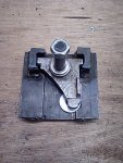
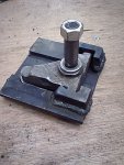
The New Bandsaw...............

Not out of round, it is wobbling side to side.

I'll give it another look tomorrow, 4AM bed time! :wave:

The side to side wobble isn't terribly unusual or a big deal really. As long as you crown the tires properly, it really won't matter much what the wheel does (within reason). Bottom line, the blade follows the crown, and as long as that runs true, everything will be fine.

-Bryan
 
Well, the man in the brown shirt arrived today, much to my surprise, as I got the "Shipping Confirmation" e-mail yesterday... :eek:

Yep, UPS guy with my shipment from LV! :thumb:
Blades, spring, wheel brushes, cool blocks!! :D

With a new blade on there, it runs a lot better, but I think I've found the trouble, the pulley on the drive shaft, not the one on the motor, but the one on the bandsaw, on that is driven by the motor is WAY wobbly, out like 3mm wobbly.

I think this is setting up a vibration in the bottom wheel.

I also checked the shaft, and it is dead on zero, no movement at all, so that is good!

More later, with pics! :wave:
 
OK, got a new video up, this shows the slack in the top wheel tension/tracking adjuster (with no tension on the blade) and it shows the runout of the bottom wheel......

The Phoenix Part II Wobbly Wheels

While I'm showing you all stuff, here are a couple more pics.....

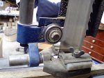
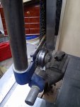
big_blue_bearing1.JPG big_blue_bearing2.JPG
Pics of the bearing on the back of the blade on Big Blue, this is how Tod is suggesting I set up the bearings on the Phoenix. BTW, Big Blue only has one of these, there is no bottom bearing.


Next up, I was curious how "Stiff" my saw frame on the Phoenix actually is, so I put it to the test with the NEW cobra coil spring in place, and a 1/2" wide blade (I think 1/2" is as wide as I'll ever run on the Phoenix, as I have Big Blue for most everything that requires a lot of saw).


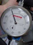
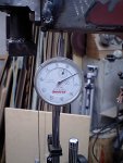
Here is the dial indicator zeroed in..........
flex_test_zero.JPG
Yep, that is on Zero.

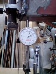
Next is a shot showing how I set everything up for the test.....
flex_test1.JPG
...ready to put some pressure on the frame!!

flex_test_2.JPG
Here is the dial indicator showing 0.20mm of flex, this is as tight as I'd ever run the saw, maybe even too tight, I think that is about 8 thousandths of an inch, not bad?? :dunno:

flex_test_3max.JPG
I then cranked the crank to the point that the spring was completely squished (I only did it for about 20 seconds!!) and I got 0.30mm or about 12 thousandths of an inch.

Should I be pleased with this result?

Dunno, I guess I'll have to test Big Blue and see how he does :D

if any of you guys with a 14" saw and a dial indicator want to test your saws and share the results here, that would be cool too!

Well, did you like the video? :rolleyes:

Cheers!
 
Is the wobble the wheel on the shaft? Or the whole mechanism mount? If on the shaft, can you shim it to take out the slack? Or is the surface the shaft rides on at the wheel damaged?
I'd think that kind of movement in the blade would make for some inacurate cuts, as far a where to stop on non thru cuts. And really hard to set the thrust bearing!! :D
Good video! Seeinig always helps. Jim.
 
We are talking about the top wheel tension/tracking adjuster, right?

The slop is in the two shafts that go from the aluminum piece that holds the spring and rides up and down in the saw, and the roughly triangular piece that the shaft for the top wheel is mounted on.

Basically the holes in the aluminum piece are too big, so the steel shafts in thre triangular piece are not tight in place.

I will see if a new drive wheel pulley makes a difference, but I think I will end up drilling some new slightly larger holes and putting in new shafts.

Cheers!
 
stu, the video helped me understand the wobble that you spoke of....with the lower wheel you might be able to flex it somewhat? but i`d worry about breaking or weakening the aluminum spokes...the upper is obviously in the mount, and me thinks that given the warp in the lower wheel and the slop in the upper you might have some tracking issues? as far as a fix goes i`d build an upper adjuster from scratch and get rid of the slop and check on availability of another wheel for the lower with the same bearing races.....by fixing the upper mount you might not notice the wobble in the drive wheel? most of a bandsaws personality comes from the driven wheel not the drive so by only addressing the upper you might fix the issue?
the frame is plenty stout!;)
 
We are talking about the top wheel tension/tracking adjuster, right?

The slop is in the two shafts that go from the aluminum piece that holds the spring and rides up and down in the saw, and the roughly triangular piece that the shaft for the top wheel is mounted on.

Basically the holes in the aluminum piece are too big, so the steel shafts in thre triangular piece are not tight in place.

I will see if a new drive wheel pulley makes a difference, but I think I will end up drilling some new slightly larger holes and putting in new shafts.

Cheers!
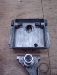
Or if that becomes the "right" fix, drill out the hole, and add some sort of bronze bearing insert or similar? Maybe something that could be replaced if need be in the future. Jim.
 
Well, I took the top wheel tension/tracking adjuster thingy apart again, with the idea of trying to drill it out and fix it, remove the slack in the unit.

Here is the unit in pieces......
tension_tracking_adjuster_parts1.JPG

and the two shafts in place.....
tension_tracking_adjuster_parts2.JPG

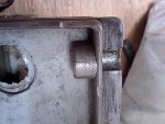
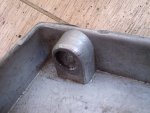
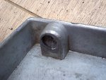
Upon closer inspection I found this......
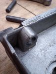
tension_tracking_adjuster_cracks1.JPG tension_tracking_adjuster_cracks2.JPG tension_tracking_adjuster_cracks3.JPG tension_tracking_adjuster_cracks4.JPG
Well shoot, that one side is all cracked to heck, no fixing it either :(

OK, I'll be making a whole new one, out of steel, I'll still use the roughly triangular piece that has the shaft on it for the upper wheel, as finding a shaft like that would be difficult.

Oh well, this piece was always the weak link in the whole saw, so I guess I'm better off if I just make a new stout one........... right Tod :D :wave:

I'll get to that first thing in the morning, so I'm for bed now, got lots going on this week, Dungeon time has been limited :doh:

Cheers!
 
stu, how is the axle mounted to the pot metal? if at all possible ditch all of the pot metal or aluminum or whatever it is and go with steel or cast iron....steel with some zerks would outlive you and i combined...
 
Tod, the piece the the shaft is in, the triangular bit, is decent steel, weldable even. I put a roll pin in it to hold the shaft, made sure it was square, and then welded the shaft into the piece, it is not going anywhere.

I think I'll take Jim's advice and drill out the holes in that piece, put a brass plug in it and then re-drill the right sized hole, and use some of the nice drill rod I have from making lathe tools for the shafts, this should make a really nice tight fit.

The aluminum part is the problem.

Cheers!
 
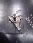
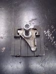
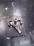
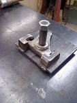
Well, I got some fabricating done! :thumb:

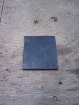
tta1.jpg
To start with, I made a piece of steel 6mmt thick, 87mm wide, by 100mm tall. Flat and square on all sides. Took some time with the 4" angle grinder and some file work.

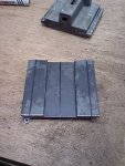
tta2.jpg
Next up were the "wings" these are the parts that will go into the frame of the saw and be captured there, and let the tension/tracking adjuster move up and down.

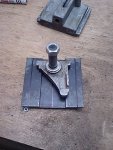
tta3.jpg
Now, I have to relieve some of the wings to make room for the shaft holding piece.

tta4.jpg
OK, there, the first parts are relieved. I'll have to build these up a lot more, so I have some meat to drill holes in.

tta5.jpg
Now some thicker pieces have been ground out so they fit.

tta6.jpg
Now I added another layer of 6mm thick steel, this will give me lots of meat to drill into.

tta7.jpg
Ready for some time in front of the electric sun :wave:

tta8.jpg
Welded up, still needs some grinding and filing.....

tta9.jpg
...then I'll have to do some drilling.....

Drilling the holes for the shafts is going to be the most important part, I've measured the holes that exist in the shaft holding part, and they are just over 8mm, about 8.2mm. My plan is to go buy two 8.2mm drill bit and drill the holes in the new part, then use the solid parts of the drill bits as shafts for the unit, most likely cheaper and easier to do than try to find 8.2mm drill rod :rolleyes: :D

The next thing I have to do, after drilling the holes, is build a spring box on the back of the unit, that is not going to be a big deal.

This went a lot better than I thought it would.

Cheers!
 
Looking good! It will be better that anything you could have purchased! Jim.

That is the plan! :D

I figure not counting blades, as they are consumables, IMHO, the whole saw, minus the motor will cost me right about $200+- the motor could cost me that much again :dunno:

Still for $400 and some of my time, I think I'll have a good saw, I hope I'll have a good saw :rolleyes: :thumb:
 
Top