The New Bandsaw...............

Looking Good, Stu. I wrote up a couple of Ideas for what I believe would be an improved Dust Collection setup for you a few days back,:type: but just as I tried to post it our IPO went belly up and was down for several hours and I lost the whole thing.:doh: :(

Right after that you discovered the problem you're currently working on, so I won't bore you with the DC details right now, but will try to repost them after you get your wheel system finished. What I have in mind would use some of the current Mfr's design thinking, but with a couple of small changes/additions that I believe would effectively improve the collection. Anyhow, it will give you some food for thought, and maybe others will chime in with their thoughts on my idea as well.:dunno:

Gotta go now, since a friend over in Midland that's been working out of town for a long while is home, and invited us over to help them eat the Pork Ribs he's got cooking in the smoker, (smoked with Mesquite of course, what else in Texas)? :thumb: :D

Have a nice weekend.
 
Well, I have to say, I had a good day, and a bad day, and finished with a sort of good evening.............. :rolleyes:

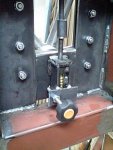
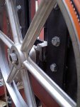
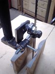
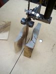
I finished up the tension/tracking adjuster, rock solid, and built to last, works great!!! :thumb:

new_tension_tracking_adjuste1.JPG new_tension_tracking_adjuste2.JPG

But then I got a little crazy trying to get a 1/2" blade to stay on the wheels, I tried everything, tweaked everything I can think of............. :huh:

The wheels are square to each other, running straight and true, are deal coplanar and still, the darn blade would NOT stay on the freaking saw :bang:

I've checked and rechecked EVERYTHING I can think of...........:huh::dunno:

I was about to give up and go get a case of cold beer from the L shop and frogetaboutit............ :rolleyes:

Well, as a last ditch effort, I tried another blade, a thin one................ yep, worked MUCH better.

I've come to the conclusion that the problem is the wheels and tires.

The wheel are dead flat on the rim, the place where the tires go, and being them GOOD urethane tires, they are also dead flat, and not crownable :doh::wave:rown them, I'm convinced that this will solve the problem.................

Here is some sawing in some pine.....
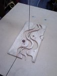
curvy_cuts.jpg

No blade guides top or bottom, or blade bearings at all.

Not too shabby, I think :D
 
Last edited:
"Crown them, I'm convinced that this will solve the problem................."

Stu,
Before you ruin a good set of tires, try a different half inch blade. Most 14" saws - mine included - have flat (not crowned) tires on them, and work quite well with half inch blades.

I think you may have a bad blade - maybe one that has a weld that's not aligned properly.
 
I see you're running into the same problem with wheels and bearings that I had. I ended up with 1 1/8"OD x 1/2" ID wheel bearings spaced 1" apart on a thicker, heavier, wheel (no spokes), which I had to design, cast, and machine myself; these are the idlers (2). The castings have to be sturdier than any available commercial wheels if you intend to run the enormous tension you seem to be designing toward. Likewise, the drive wheels I use are precisely machined heavy cast aluminum with keyways. They are then statically balanced to reduce the vibration inherent to machined castings. The wheel mountings will have to be adjustable for planarity yet feature a slide mechanism (tricky, that) to allow "forgiveness" to deflection. (Or you'll break blades constantly) You'll also need two standard BS springs incorporated into that slide mechanism if you intend to run high tension, or you'll bottom out immediately and lose the whole concept of "tension".


I also see you decided to attempt 16" cut depths with blades of under 3/4" width. Assuming you corrected the wheels' shortcomings and produced a high-tension transport system, you will then be faced with the deficiencies that commercially available blades, themselves, present. To get a narrow-kerf blade to run flat through 16" of stock you'll need so much tension that the tires will "furrow" in the center and the blade welds will start to show their vulnerability, too. I thought I had hit the "ceiling" there but when I started investigating the blades' dynamics and experimenting with pitch and set designs, it became apparent that there are NO blades available for that purpose. You have to make your own. Doing so led me to designing my current re-setting machine (now in its fourth evolution). It's been a real eye-opener. My little portable mill now cuts as fast as a full-on saw mill, still using the same 3/4 HP motor. The secret is in the blade set pattern.
I haven't got the brochures made up and a separate website devoted to re-set blades will be forthcoming when I finish the cross-reference charts for deep-cutting solutions. The 2TPI re-setter is fully operational now and my Falberg saw customers are already raving about it. The 3TPI (still fast, but smoother finish) machine is almost finished and those blades will be available within a month. My 1/2" wide-set blades cut smooth, straight, 3/4" radii now and the narrower version cuts arches like a raped ape. (And you know I never brag.) ;<)
Call me when you get the saw running and you can try some "designer" blades.
I'm watching with great interest what you'll do for a table. Being primarily portable in nature I haven't really designed anything fancy in that department so your mounting solution will be noted.;)
Regards, Bill
 
And, yes, you'll definitely need to crown the wheels at an arc that would project out to a spherical contour. In other words; the crown's radius should be the same as the wheel's radius; like a ball. The blade will then find TDC no matter how "off" the wheel wobbles, nor how much deflection you introduce. Especially running without the BG's.
PS: Now that I see your tensioner I have to revise my estimation of your tensioning goals. Maybe those wheels will work; as long as you don't get too ambitious with that spring.. ..
Again, good luck,
Bill
 
Stu, on my MiniMax E16 with flat tires, I can track a 3/4" blade, but more of it hangs off the lower wheel than it should. A 1/4" blade comes off the wheel...will not stay on. Sam has the answer for mine, I know it will work, I just haven't implemented it yet. The lower wheel needs to tilt a little to track further toward the middle so the blade just hangs the teeth over the wheel. My top wheel adjusts and tracks perfectly.
Is the blade popping off the front of the tire, or to the rear? I don't know if that will make a lot of differnce, but it might make a difference for the bandsaw gurus we have here. Maybe it will trigger the answer. Or maybe that one blade is a bad blade? Jim.
 
Thanks for the "You gotta crown the tires" info Bill, it makes sense to me, but....

I'm not saying it cannot work with flat tires, just that it should work better with crowned ones.

I think I have to come up with a way to have the bottom wheel more adjustable, I have slotted holes and some shims right now, not the best thing.....

I need to work out a more adjustable mount for the bottom.

Cheers!
 
I don't believe that crowning is necessary, just the right tweaking that you haven't quite hit yet, seeing as how the Italian Bandsaws run flat tires, and are reputed to be at least "Among" the best manufactured bandsaws in the world today. Does the blade run off the wheel toward the front, (the infeed side), or to the rear, (outfeed side)? Not only the tilt of that bottom wheel, but it's position foreward or backward at the 3 and 9 o'clock position can also affect it with only a very minor adjustment. The adjustments of each of these axis' can/will affect the other. It would be easy to quickly see what needed to be adjusted if you had a bar with a nut welded on the end that you could screw onto the arbor inplace of the arbor nut and then you could put pressure up down and right/left as the wheel turned and watch the tracking to see how it was affected by the movement in each direction.

Hang in there, Stu, you'll get it right.
 
Last edited:
Thanks Norman, and I think I finally did get it right............ about time eh? :eek:

My major problem was with getting the wheels coplanar, I thought I had this down pat, but, I was doing this with the tension off the blade..........:huh: Don't ask me why, I'm just STU-pid sometimes :rolleyes: :rofl:

When I did it with tension on the blade, it was obvious I was out, a bunch. The fix ended up being to move the whole tension/tracking adjuster inboard by about 1 cm and this let me get things straight.

I' able to now run the 1/2" blade.

The major problem I still have is the massive vibration from the drive wheel pulley, it is bent bad enough to be really causing a problem :doh:

I've got a new cast iron machined one on order :thumb:

An "Update" video is in the works....

Cheers!

Hey, I'm glad you figured it out. I started to ask if you checked it with tension on the blade, but I thought ......naaaaaah, he knows to do that.:D
Sometimes the obvious things aren't all that obvious when you're tired and have been too close to the project for a while.:huh: :doh::D Glad to hear that the vibration is coming from the pully and not one of the wheels, as those would probably be a lot harder to replace, (and for sure more costly).

Now for a question of a different nature. How do you guys draw those lines and pointers on the pictures you post when you are trying to point out something in the picture? If I knew how to do that, it would make it a lot easier to describe my ideas for the DC setup on a bandsaw. I'll try to get that written up again later this afternoon, AFTER I take care of some plumbing problems, (water leaks) in the maze of tubes and piping under the kitchen sink that is way overdue and causing the LOML to get a "wee bit" tight jawed about the situation.:(
 
I use an image editing software called Ulead PhotoImpact.

You can download a 30 full trial from their site.

there are a lot of other ones out there, but I like it, as I've been using it for a long time, and I have found it rather intuitive.

Cheers!
 
OK, Stu, here goes a try at explaining my DC ideas. It is a two part approach, the first being to duplicate what you saw from Tod and Marty's pictures of that little angled metal box with the slide in plywood ZCI and a DC outlet off of that on the right side as you're looking straight at the wheels from the infeed side. I would suggest though that you install a blade brush in there though on the left side of the blade and about 1" above the plywood ZCI.

Now for the second part. I managed to find a program called Paint, and I drew a VERY CRUDE sketch on a picture of your saw with what I have in mind, Buuuuuuut.......I don't know how to get it from My Documents into this Post, so I will just email it to you for you to see, and if you want to insert it in the thread, that will be ok too.

What it amounts to, is to cover the area behind the lower wheel with a thin sheetmetal (Backing Plate), (like you made your cyclone out of), and then make a shroud that curves around the bottom wheel about an inch or so away from the wheel with an outlet at the center of the shroud below the wheel. I would also suggest another blade brush on the right side of the blade about 1" after the blade first contacts the bottom wheel. The shroud should be somewhat curved across it's width as well as following an enlarged wheel radius curve, and the shroud should be sealed to the backing plate, and extend to touch the Door (with a soft rubber seal).

I know this is not a very good description, but maybe you will understand it better when you see the "Very Crude" sketch. I'll send the sketch as soon as I post this.

Cheers
 
Norm, I got your mail and your pic, I see what you are saying, bacially the dust shroud is around the lower part of the wheel, inside the door that covers the wheel, and having the dust port for the hose at the bottom lets gravity work for me too.

Good idea, thanks!
 
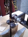
OK, got some work done on the upper guide, well I guess it is basically finished......

upper_guide_front_side.jpg

I know things look a bit rough, as they have been roughly shaped and welded, then ground. I'll make sure it all works, then do a bit of filing and sanding to make it nicer.

I'm using the cool blocks, and the bearing at the back turned so it runs like Tod suggested.

upper_guide_head_on.jpg
A head on shot

upper_guide_rear.jpg
A shot from the rear. The bolt on the side locks the blade guide shaft in place, while the nut on the end sets the position of the guides. I'll build some kind of a handle for that nut, so I can turn it easily by hand, same with the locking bolt, needs a handle of some sort.

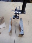
upper_guide_curvy_cut.jpg
I did a curvy cut on this dry hard piece of Akagashi (Japanese Evergreen Oak) it's about 4" tall, cut through it with ease.

There are no bottom guides or thrust bearings on the saw, yet.

Well, how did I do? :wave:
 
Top