Kitchen Cabinets - New Door Stiles & Rails

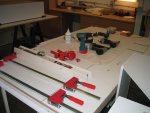
It is time to put all these parts together. Here are all the parts, except the back laid out on the assembly table.
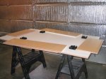
Cabinet 41.jpg

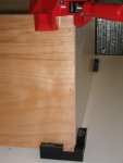
Because these butt joints will be glued in addition to being tacked with staples and then screwed, I needed to sand off the pre-finishing at the joints to help the glue adhesive.
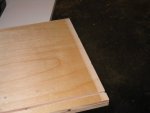
Cabinet 46.jpg

Talking about glue, I used Roo Clear glue on the recommendation of Tod Evans and other web sources. It is specifically made for melamine, but some web sources suggested it for pre-finished ply.

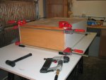
I glued up the bottom to the two sides and secured with clamps. I also secured the joint with staples where the side is not exposed.
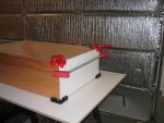
Cabinet 48.jpg Cabinet 50.jpg

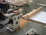
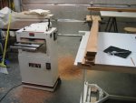
A short intermission to show my setup of tools during this whole process. Everything at hand that I need.
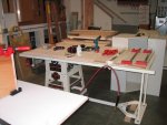
Cabinet 34.jpg Cabinet 35.jpg

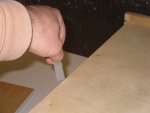
The next two pictures show working on the other end. You see that I have slid the back in the groove (after gluing sections of the groove). You will notice a small flap of something at this end of the back. That is translucent tape like you use in a office. It is there so that when I install the last component (the top) I can guide the back into the tops groove. You will notice that the 1/4" back sags a little and without a way to pull up on the back at the center there I would not get it in place.
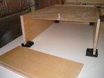
Cabinet 27.jpg Cabinet 51.jpg

Here is the top in place.
Cabinet 33.jpg

I hope to show the completion of the assembly later tonight. It will be drilling and screwing the joints.
 
Last edited:
Even though I have glued and stapled (to hold the joint in place) the boxes, I always planned to install screws. Maybe it is overkill, but considering that I am replacing kitchen cabinets that failed you can probably understand my paranoia.

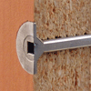
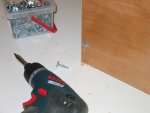
I used Powerhead screws. They have nibs under the head which if used with a impact screwdriver will allow you to seat the head flush with the surface. Their design actually prevents you from overdriving the screw and sinking it far below the surface as you can with a regular wood screw.
Powerhead Screws.gif

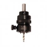
I decided to use a Flushmount Drill Bit that has uses a unique ball bearing stop collar that controls the recess depth of the drill. You can really fine tune the depth. When you reach your depth the drill stops spinning so that you do not mar your finish. It worked very well.
Flush Mount Drill Bit.jpg

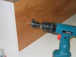
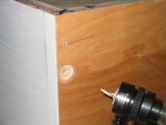
This is what it looks like mounted on the drill and what the hole looks like on the cabinet.
Cabinet 37.jpg Cabinet 38.jpg

A picture of the screw installed.
Cabinet 39.jpg

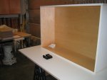
Here is a picture showing the finished interior of the box.
Cabinet 36.jpg

I hope to show the installation of some of the cabinets on the wall tomorrow.
 
Mounting the cabinets

I thought it was bad when I had all the upper cabinet components cut out and stacked through out the shop, but when I built the first 4 boxes I developed a better idea of what cramped really is. These four boxes are needed to be installed right away. They represent my hasty action without a plan, resulting in kitchen stuff all over the place.

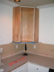
I installed the corner cabinet first and worked out.
Cabinet 56.jpg

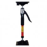
As you can see I am using a lift device called the Little Hand HD. Here is a close up of it. It worked very well. You have a quick adjustment and also a fine adjustment so that you can sneak up on the correct elevation.
LittleHand1.jpg

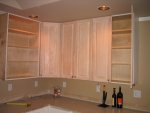
One thing I failed to show was the installation of the "nailing strips" on the boxes. They were 3/4" plywood about 3" wide and were the same length as the inside width of the boxes. I attached these with pocket screws. The back for the corner cabinet was solid 3/4" instead of the 1/4" on the other boxes, so no nailing strip was needed or used. Below are the cabinets with the doors attached. The doors were stripped by my wife. The one cabinet is missing a door because that cabinet is replacing a cabinet that was 48" wide. The doors obviously will not fit. I will need to build new doors for this cabinet (another posting). If you look closely you may see that the corner cabinet door is just not wide enough by about 1/4 inch.:dunno: I don't know how that happened, but I will need to build a new door for that cabinet also.
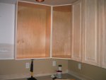
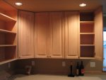
Cabinet 59.jpg

Cabinet 66.jpg

Cabinet 67.jpg

Cabinet 64.jpg

I am going to finish this thread with one or two more posts showing building the doors for these two cabinets and will stop posting on this build. Once I have completed the rest of the kitchen I will do a final post showing the end result.

P.S.
The doors will remained stripped until the rest of the cabinets are completed, as I am going to have a commercial shop paint all the doors and drawer fronts. I have a spray rig, but I want them sprayed with really durable "paint" that I don't have the facility to spray.
 
Bill, did your LOML cut off your food til the cabinets are finished, 'cause you are really making fast progress on that project. :D Lookin' very good Too. :thumb:

Since your corner cabinet came out a little wider than the door, I now know where that mischievous little "ELF" went that usually hides in my shop and occasionally sneaks out and resets the TS Fence.:rofl::rofl::rofl:
 
hey bill, looking good. i feel your pain on the door not fitting. i always had at least one somehow mysteriously not fit.

those corner cabinets can be tricky to figure out, especially to know what the opening will be. even harder i think without a faceframe.

good progress. looking forward to final pics

chris
 
looking good bill and your progress pics are great! shows the full extent of what goes into a job like this and you even showed us the oops that can happen aswell:thumb::thumb::D
 
Thanks everyone for the kind words. As for the corner cabinet, I had it drawn out in Sketch-up so the mistake was not there. I must have not used the correct measurements when I cut out the top and bottom. It is no big deal, as I have made doors before and have worked out all the kinks. Actually the doors is more like the woodworking I like than building boxes. Not that building accurate boxes is necessary easy, it just takes a very meticulous approach and accurate setup on your machines. There is no fudging with a hand plane to make it fit. The guys that do this for a living have my utmost respect. I just need to git er done.
 
Last edited:
Trying to re-use the old door.

I have to make three new doors for the upper cabinets. Two for the W12x27x42 cabinet that replaces the 48" cabinet that I am no longer duplicating (see postings above to explain why)(The other door is for the corner cabinet:eek:). The doors on this old cabinet are each approx 24" wide.
Door Panel 1.jpg
In trying to save some time and make use of the old doors, I had the thought of just cutting a middle section out and gluing the remaining sections together. This would make a new door with the proper width needed for one W12x27x42 cab door. I cut out the section with the table saw. Putting the remaining sections together it quickly became obvious that trying to get the rails to fit together and then the panel, just was not going to work. I had just too many varied surfaces to deal with. There would be many uneven ridges in the glue joint that I would have to do something with.

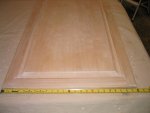
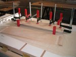
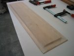
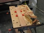
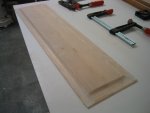
Well, how about just trying to salvage the panel portion of the doors? I thought this would work so I pried each section of panel from their stile and rail and then glued them together. Below you can see the panel in clamps and next to it is the cast-off center section.
Door Panel 2.jpg

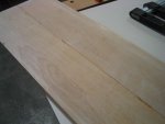
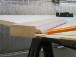
Below is the result of the glue up. There is a ridge where the two sides joined because the panel was not even all the way across. I just tried to keep the front flat during the glue up. You can see the small ridge in the picture below.
Door Panel 4.jpg

No problem for me, I just got out a hand plane and made sure the front and back were nice and flat. Of course when I went to take pictures of this, the camera batteries decided to take a short break. So while I charged them up, I finished this operation.
Door Panel 3.jpg

I got a little tear-out during the flattening process, so I grabbed one of my card scrapers to take care of that
Door Panel 6.jpg Door Panel 7.jpg

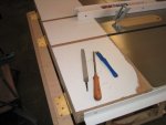
Below is a picture of my tools for sharpening and burnishing a scraper. They are a lot of methods out there for doing this, but I follow Rob Millard's instruction because it is simple and does not go overboard. http://rlmillard.typepad.com/my_weblog/2008/03/sharpening-the.html

The only place where I differ is that I secure the card scraper in my vise and hold the file in my hand. It works better for me.

Door Panel 5.jpg

I only glued up one panel because I need to test this with the new stiles and rails I will make. The cope and stick router bits I have may not match these existing panels exactly. If it does than I will be salvaging the panels out of two more doors.
 
Last edited:
Not the edge but the sides, some people even use their waterstones to do this. You do this to remove the burr on the face after you file the edge. Check out Rob Millard's website.
 
Stiles & Rails - Wood Prep

My last post was about salvaging the panels from the existing doors. This post and the next will be about building the stiles and rails for the new doors.

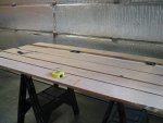
First step is laying out all the stiles and rails without wasting wood and avoiding as many defects as possible.
Cab Door Prep 1.jpg

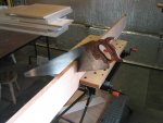
Here I am crosscutting the rough lumber to make it easier to rough rip it on the tablesaw. I just find it safer to rip it in shorter sections. That is a Disston D-23 in the picture. Really comfortable handle!
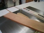
Cab Door Prep 2.jpg Cab Door Prep 3.jpg

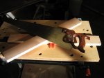
After rough ripping the wood, I crosscut the rails (using one of my D-12's) to approximate size before running everything through the jointer to get a flat face. I then thickness plane everything, but did it in two stages. I did a couple runs through the planer (flipping sides to make sure to take cuts from both faces) and let it set for a day to see if it would move. I then finished up to the final thickness. I know it seems kind of time consuming, but I had a bad experience with planing a lot off in one setting once. If the wood moves that much, I probably would not use it anyway, but I would rather save all that planing time and know. I don't mind waiting a day.
Cab Door Prep 6.jpg Cab Door Prep 4.jpg Cab Door Prep 5.jpg

Using my smoother and a card scraper I cleaned up all the machine marks and any tearout. Nice thing about hand work is that it keeps you warm!
Cab Door Prep 7.jpg Cab Door Prep 10.jpg

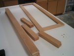
The picture below is after I have final ripped and crosscut all the stiles and rails. They are now ready for routing the sticking and coping which will be the next post.
Cab Door Prep 11.jpg
 
Stile & Doors - Sticking and Coping

Now that I have the stiles & rails cut to proper size and thickness, it is time to router the stick and cope joints. I have a Whiteside stile and rail set that closely matches my existing cabinets. I bought this because some time back I modified a cabinet above the refrigerator and had to make new doors for it.

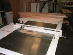
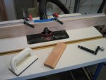
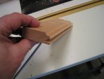
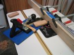
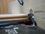
Most instructions that I have seen for other router bits have you start routing the cope joint, but Whiteside is different in that their instruction tell you to do the sticking first. In my test piece below, I am just trying to make sure that I have about 1/8" on the back side of the groove for the tongue and groove joint. If it is too thin, it might break off. You can see that I have just the right amount left on the backside.
Cab Door Route 1.jpg Cab Door Route 2.jpg

Just a little background on my router table system. It is a Woodpecker table and fence system. It also has a Woodpecker Quick Lift which makes it a joy to use. A lift makes all the difference. Trying to make a fine adjustment without a lift was exasperating, especially with my old Porter Cable 690. That old 690 was replaced last year with a Milwaukee 5625-20. More than enough power to spin any raised panel bit.

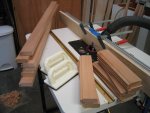
Below are the stiles and rails run through the sticking bit.
Cab Door Route 3.jpg

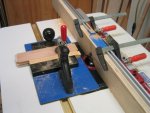
Now comes the trail and error part, matching the coping bit with the existing sticking profile. It really is not that bad, after doing a rough set up with the wood on my coping sled, I needed only one adjustment and I got it nailed perfectly.
Cab Door Route 5.jpg Cab Door Route 6.jpg Cab Door Route 7.jpg

Here I am running one of the rails through the bit.
Cab Door Route 8.jpg

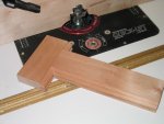
Below I laid out a door stile and rail to show what it looks like.
Cab Door Route 9.jpg

You may remember a couple post back that I salvaged the existing panels from the old doors (with some modifying). Well when I started looking at the sticking that I produced, it became very apparent these panels will not work with the Whiteside bit set. The panel tongue is just too thin for the Whiteside groove.
Door Panel 3.jpg Cab Door Route 4.jpg

Well, it was a good try. That just means I need to start prepping wood for some new panels. That will be for another day.
 
ok bill why does whiteside reccommend that you do the sticking first rather than the cope cuts? and how do you like those bessy corner clamps.. and onemore question what are those black corner pieces ,,i can see how you used them t have never seen them in any catalogs???? good job thus far and great explantion of it!!!1
 
Top