G&G Inspired Chest of Drawers - Build Thread

Very nice touch. I really like the idea of edging with a contrasting color wood. :thumb::thumb: Instead of trying hide an edge piece by making it the same wood and having a join line the contrasting wood detracts from the fact that there is an edge. Kinda shifts the focus. Well at least if you a woodworker.:D

Once again i picked up a good tip from your pictures.

I never gave it a thought to set up a block with each grit of sandpaper on. :eek: Cool idea i bet you aint the only one to do it. :thumb:


Glenn i see you really moved your rails over on your TS. I did too but i dont think i went as far over as you. Now what keeps the router table up against the TS edge. You got a few brackets under there or they just standing shoulder to shoulder?

Btw I feel relieved now i saw a little dust on your saw for once.;):rofl:
 
Very nice touch. I really like the idea of edging with a contrasting color wood. :thumb::thumb: Instead of trying hide an edge piece by making it the same wood and having a join line the contrasting wood detracts from the fact that there is an edge. Kinda shifts the focus. Well at least if you a woodworker.:D

The contrast probably won't show and you'll see how that happens as I get farther along. Hard to explain, easier to show, eh?

Once again i picked up a good tip from your pictures. I never gave it a thought to set up a block with each grit of sandpaper on. :eek: Cool idea i bet you aint the only one to do it. :thumb:

It's the only way to fly :)


Glenn i see you really moved your rails over on your TS. I did too but i dont think i went as far over as you. Now what keeps the router table up against the TS edge. You got a few brackets under there or they just standing shoulder to shoulder?

Btw I feel relieved now i saw a little dust on your saw for once.;):rofl:


Rails shifted one hole (10" - no drilling required) for a bit over a 40" capacity. It looks farther because the left wing is still present between the saw and the router table. I sank threaded inserts into the edge of the router table top and drilled holes in the outer edge of the wing. I use the adjustable feet to position the router table right where I want it and then thread in 4 bolts from the underside/backside of the wing to keep things snug. ;)
 
Last edited:
I am always trying new methods to improve the consistency of my efforts. I have a sharp edge on the short rails that needs the customary G&G roundover. On end grain I find that sandpaper used for the initial shaping was leaving me a lot of work. I take end grain to 600 grit as it seems to give me more consistent color and yields me that soft gloss I like when finished.

I tried a low angle spoke shave and a shoulder plane to get the rough shape with pretty decent success. I'll use this method for a few more and see how it goes.

CoD sides shape and assemble 1.jpg CoD sides shape and assemble 2.jpg CoD sides shape and assemble 3.jpg

I want the transition from one flat plane around the . . er . . . roundover to the other flat plane to be seamless in appearance. A wipe of mineral spirits tells me when I'm done. Thanks to dear old dad for the tip on keeping some mineral spirits in a spray bottle handy during these steps.

CoD sides shape and assemble 4.jpg CoD sides shape and assemble 5.jpg

For long grain these inexpensive, shaped sanding "blocks" still seem to be the best bet. I use them after knocking the corner off with a couple swipes from a block plane or really whatever is handy.

CoD sides shape and assemble 6.jpg

Note to self: dry runs of your glue-up procedure are important, not optional. Especially when you're a goof like me and you have 8 tenons and 4 parts to do in one run. I found during the dry run that I would need a couple extra items that I would have been thrashing around to get to if I had not taken the time to prepare :rolleyes:.

CoD sides shape and assemble 7.jpg CoD sides shape and assemble 8.jpg

When the clamps are applied the assembly has a tendancy to want to rise up like a hump. The extra pressure points bring everything into line on a nice flat plane.

CoD sides shape and assemble 9.jpg

Being all proud of myself, I forged ahead without realizing I was doing the glue up right where I needed to work on the next set of side pieces:eek:. I should have done this on another surface. I'll give it 30 minutes or so and then transfer it over to another table so I can continue.


1328
 
Last edited:
This is a stage where a lot of effort goes in but very little progress shows:huh:
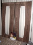
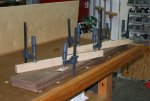
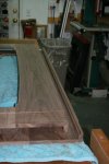
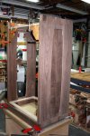
. Just so you don't think I've wandered off. The sides are glued up and just short of final shaping. Tonight I milled these four pieces to 7/16" and will let them set a bit before milling to the final 3/8" thickness. They will make up the split side panels. Due to the construction sequence, these panels will be installed prior to assembly of the sides to web frames. I am waffling as to whether to finish them prior to assembly or not. I am leaning toward finishing as the panels float in the sides and in relation to each other and I don't want any peek-a-boo unfinished surface or ridges of finish showing up as the seasons change.
 

Attachments

  • CoD sides shape and assemble 10.jpg
    CoD sides shape and assemble 10.jpg
    107.1 KB · Views: 47
  • CoD sides shape and assemble 11.jpg
    CoD sides shape and assemble 11.jpg
    106.2 KB · Views: 51
Quote " I sank threaded inserts into the edge of the router table top and drilled holes in the outer edge of the wing. thread in 4 bolts from the underside/backside of the wing to keep things snug. ;) "

Neat and sneeky thanks. Now why didnt i think of that:doh::eek: Its that old "Stout" word. Why i would think i want the thing to be tied together so secure that a hurricane would not seperate em is a mystery to me but just look at what i build for gates.:rofl::rofl: And i wonder why my projects cost me so much more.:eek::huh::wave::rofl::rofl::thumb:

Thanks


Now i learnt two or more things from this latest post. I see you and Gary have a head start on those in between clamps. Cauls would be difficult to use in that glue up and that add on is perfect.

What make is your clip on clamp Glenn i see the handle is blue not red?

And mineral spirits. Somehow i thought that it was in the turpentine category of solvents, and left a oily kinda residue so i have been using acertone for that kind of thing but it does stick around long enough to take a pic. Great tip to put it in a spray bottle.:thumb::thumb: No ways Jims brains have leaked.:D
 
ok glenn,, where did you get those down pressure clamps with the blue handles??? yu keep spending my money:) thanks for the in depth on this project enjoying the build..
 
ok glenn,, where did you get those down pressure clamps with the blue handles??? yu keep spending my money:) thanks for the in depth on this project enjoying the build..

Money is always a concern so you'll love this; I got those for $2 each at Harbor Freight years ago. I have some of the double screw models too. Handy for edge work. The "real" versions (Bessey, etc.) are prohibitively priced for me ;-)
 
Money is always a concern so you'll love this; I got those for $2 each at Harbor Freight years ago. I have some of the double screw models too. Handy for edge work. The "real" versions (Bessey, etc.) are prohibitively priced for me ;-)

can you give me a pic of the ones you have there so i can see how they got the part to attach to the bar clamp?

went to look for them and found nothing glenn???
 
Last edited:
I also can't find them on their website. I hope they still have them, for some unknown reason I only bought three??? I'll snap a pic when I get home.

Later that day . . . . .

Here you go.
 

Attachments

  • edge clamps 001.jpg
    edge clamps 001.jpg
    66.4 KB · Views: 38
  • edge clamps 002.jpg
    edge clamps 002.jpg
    53.8 KB · Views: 39
Last edited:
I've been waiting for this. Sketch Up and our vivid imaginations aside, there comes a time in many of my more involved projects when I get to see something life size and right there in front of me.

I've found that after awhile, I have so much odd stuff around that I can rig almost anything in a short period of time. The hardboard splines need to be pretty accurate for this so I wanted some featherboards:

CoD sides shape and assemble 12.jpg CoD sides shape and assemble 13.jpg

I use the "Groover" blade that is normally reserved for miter splines to cut a 1/2" deep by 1/8" wide groove in the 3/8" floating panel parts. You can see how this is going together. The hardboard will be stained very dark, almost ebony looking so you'll have to picture that in your head:

CoD sides shape and assemble 14.jpg CoD sides shape and assemble 15.jpg CoD sides shape and assemble 16.jpg

Now these are just taped into position so the fit is a bit loose. I was anxious to see if my design was a flop or not so, the panel parts are right off the saw without any prep. It is shaping up like I had hoped so I am quite happy right now :). In assembly they will be held tightly in place by the "rib cage" of web frames:

CoD sides shape and assemble 17.jpg CoD sides shape and assemble 18.jpg CoD sides shape and assemble 19.jpg


1501
 
Last edited:
Rob,
Thanks for the, "No way Jim's brains have leaked." thought. Man, how I wish that were true.

Re your comment about the HF clamps. Notice the less glossy (duller) blue clamps in the background in pic #2. (Today 10-6 a bit earlier in this thread). I really do like those clamps. I even have a tendency to grab them instead of the more expensive clamps for many things. They go on sale occasionally.


Glenn,
I have to quit complementing you on FWW. People will begin to think I am one of those parents who thinks their children can do nothing that is not perfect---even if it is not.

I would like to see a pic like the last one in the series above, only from about 75 or 80 degrees away from where you took the last one. (Full length about 10-15 degrees off of straight edge...just enough to see the routed edge of the "design" and a good view of the edge.)

I know you are excellent at the occupation you have done and are doing, however, you would have made one heck of a good teacher.

JimB (dad)
 
So I'm working along and suddenly realize I forgot to rabbet the back stiles to make room for the T&G back. I'm glad I hadn't gotten past that first glue up stage or there would of been a lot more effort to "catch up". The piece of mahogany is just something for the router to ride on. As you can see, I did two passes to get the 1/4" x 1/4" profile I was after. I would normally do this size cut in one pass but, a blowout would've meant a lot of lost work.

CoD sides dado for back 1.jpg

There; much better. It was a fairly easy recovery but, I hate working on pieces once they've been shaped and scraped to a certain point. Its a great opportunity to pick up dings. It also sucked up all my shop time for tonight but, it had to be done :thumb:

1634
 

Attachments

  • CoD sides dado for back 3.jpg
    CoD sides dado for back 3.jpg
    71.6 KB · Views: 36
  • CoD sides dado for back 2.jpg
    CoD sides dado for back 2.jpg
    56 KB · Views: 35
Last edited:
why use hard board for the splines? why not use a ship lap joint instead. you would still be able to have the movement you need and and the look would be the same..
 
why use hard board for the splines? why not use a ship lap joint instead. you would still be able to have the movement you need and and the look would be the same..

+1 on the hardboard, i am suprised.:eek::D:rofl::thumb:

The panels are 41" long and only 3/8" thick. I wanted both directions to be captured as far as any bowing goes. I could have gone T&G but I feared that the 1/8" or 1/4" material at that length, possibly being asked to resist inward or outward movement (or the occasional bump and bang), might split along the grain. The hardboard is direction-neutral, dyes nice and dark and is minimally exposed in the visual sense while still capturing the look I was after :). I do understand the gut reaction though; believe me.
 
glenn, I think your day job is interfereing with your woodworking.

This project is moving along slowly, Im getting anxious to see the finished assembled project.

OK, now that's just plain mean :p

I had to go in a 5am this morning and am condemned to an irregular schedule through the weekend which is really gonna put a kink in my progress. I'm milling the blanks for the top and bottom frames tonight and that will put me in position to start the carcass glue up which will look like giant leaps of progress.

That is, till I get to the cloud lift divider and the finger joints on the frames . . . oh and the top panel and the panel frame. Now, if you want to see things really slow down from an onlookers point of view; after the carcass glue up, I start on the drawers . . . then the back slats . . . :D
 
Last edited:
are you cutting dovetailed drawers? if so, by hand?

Nope. I'll leave that to Gary Z ;). I do the G&G exaggerated finger joints and inset drawers. You can see the general idea in the Sketch Up drawing in the first post.

So, as I start to set up for the carcass assembly I really get to see what 55" x 36" x 24" looks like. That's my Grizzly G0513X bandsaw in the background for scale. It is not as massive as it felt clamping it up to this temporary position. It is just a bit bigger than the Ikea unit it will replace. I need to prep and pre-stain the floating panels before I go much further. Once the web frames are in, there's no going back.
 

Attachments

  • CoD carcass assembly 01.jpg
    CoD carcass assembly 01.jpg
    106.5 KB · Views: 35
  • CoD carcass assembly 02.jpg
    CoD carcass assembly 02.jpg
    112.7 KB · Views: 34
  • CoD carcass assembly 03.jpg
    CoD carcass assembly 03.jpg
    109.9 KB · Views: 37
Last edited:
Top