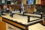
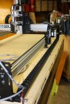
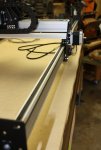
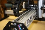
new cnc machine startover post....

Leo, not that complicated at all. I'm following the x y z axis setup determined by the manufacturer of the cnc machine, presuming they know what they're doing. Then I checked the x y z axis setup of sketchup, and found my drawings were out of alignment with the x y z axis setup
,and fixed them. Now all is in sync. No more complicated than that.
 
No problem Dan - just pointing out the stuff I see. Not trying to be a problem. Your machine is going to work fine with either axis setup.

Jay, I am quite familiar with Kitamura MyCenter - almost bought a couple of those.

I do almost all long hand programming at work, Lathe, Mill-turn and Swiss in the last 10 years or so.

I have MasterCAM at work and Vericut, but I am now using them right now.

At home I use Aspire.

The Kitty at my auction only brought $1400 it was sad to see it go so cheap. A friend of mine ended up buying it from the jerk that bought it because he didnt want the guy that bought to have it back at that price but still only paid $1500 for it.
Its been awhile that I have programed anything would need a refresher on it but it pretty easy to do long hand. When I first got the Andi with AlphCam I could program it WAY faster then there program could.

I want to look into Aspire if I can ever get me a machine built.
 
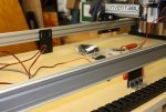
got back to it again today (technically yesterday). mounted the blade in the band saw and cut the extrusion and maker slides for the full size y axis rails, and the rail that the drag chain rides on. next is ordering the extra parts that i will need for the extended length, and ordering a photo engraving software that i've been playing around with (photovcarve). once i get the parts, its back to pop's to finish the assembly.
 
The Kitty at my auction only brought $1400 it was sad to see it go so cheap. A friend of mine ended up buying it from the jerk that bought it because he didnt want the guy that bought to have it back at that price but still only paid $1500 for it.
Its been awhile that I have programed anything would need a refresher on it but it pretty easy to do long hand. When I first got the Andi with AlphCam I could program it WAY faster then there program could.

I want to look into Aspire if I can ever get me a machine built.

I have been programming for over 30 years, as an engineer, that is part of what I do. I do a lot of hand programming, but also use CAM. I use CAM mostly at home. If you want a little help I may be able to help you.

As to Aspire - That is what I use, but I would strongly encourage you to explore the new V-Carve pro. The latest upgrade gave it some really nice 3D functionality.
 
Dan It's good to see another one of these. Should be enough to get me moving on mine again. I may have missed it but what are you using for a spindle.

I bored a hole the other day and it is pretty neat to see a little 1/8 inch single flute end mill bore a hole large enough to mount a 1/4 inch brass thread insert into complete with a flange counter bore. I hoe you love this as many projects as you build you should get a lot of use from it.
 
thanks garry!

leo - i just may take you up on that, especially when it comes time for the car cribbage boards. i have an idea or two about doing up the tool paths for the detail work.

well, with the needed parts showing up tomorrow, i've taken it apart in 3 large parts, rails, waste board, and gantry. while the wife :blah: is at school tomorrow, i'll be taking it over to pop's for fitting it out on it's bench. with any luck, it may be ready for testing on friday.
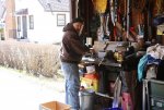
 
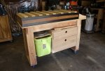
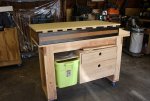
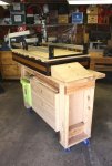
big move done today. also, one of the signs of spring has popped up, pop is tinkering at his bench again. set the waste board on the supports, then set up the machine on the waste board. it will be creative time again, as when setting it up the way the instructions show, the gantry wheels ride on the waste board. i figure that i will be securing the waste board to the bench with sheet rock screws, and with the height problem, i will have to secure the machine to the waste board with angle brackets, after tapping the ends of the extrusions. once that is done, i can finish off the wiring and such....
 

Attachments

  • 030 pop tinkering.jpg
    030 pop tinkering.jpg
    130 KB · Views: 15
  • 031 bench with supports.jpg
    031 bench with supports.jpg
    110 KB · Views: 15
  • 032 waste board on bench.jpg
    032 waste board on bench.jpg
    114.3 KB · Views: 16
  • 033 machine on bench.jpg
    033 machine on bench.jpg
    115.7 KB · Views: 18
Hey, Dan, another big step! I see what you mean about the waste board issue. I cut my waste board to fit inside the long makerslides and on top of the extrusions that support it. My gantry wheels fall outside all of that stuff. I'm sure you're pleased to be a big step closer to completion!!!
 
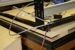
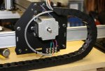
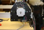
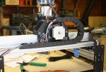
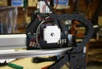
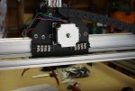
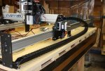
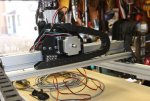
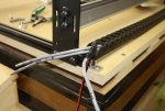
got a bit more done yesterday. got the drag chains for the x and y axis done, added the mid rail supports, added the extra wiring block and wired up the x, y, and z axis, then fed all of the wires through the various drag chains, and even though i cut the one wire longer than the other, somehow it came up a bit short. luckily i still have a long bit of wire left over, and can splice a bit of it onto the short wire. not much left to do before testing begins.
 

Attachments

  • 042 one came up short.jpg
    042 one came up short.jpg
    105.4 KB · Views: 12
  • 041 all wires fed through drag chain.jpg
    041 all wires fed through drag chain.jpg
    105 KB · Views: 13
  • 040 y axis wired.jpg
    040 y axis wired.jpg
    93.9 KB · Views: 13
  • 039 z, x axis, and spindle wires fed through drag chain.jpg
    039 z, x axis, and spindle wires fed through drag chain.jpg
    103.7 KB · Views: 13
  • 038 z and x axis wired.jpg
    038 z and x axis wired.jpg
    92.6 KB · Views: 13
  • 037 second wire block in place on gantry.jpg
    037 second wire block in place on gantry.jpg
    87.3 KB · Views: 13
  • 036 mid rail supports in place.jpg
    036 mid rail supports in place.jpg
    92 KB · Views: 13
  • 035 y axis drag chain in place.jpg
    035 y axis drag chain in place.jpg
    116 KB · Views: 14
  • 034 x axis drag chain in place.jpg
    034 x axis drag chain in place.jpg
    111 KB · Views: 15
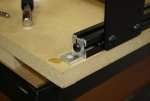
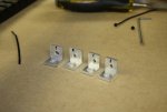
since i couldn't find the corner brackets that would fit the bill (holes too high, or too low), i picked up some aluminium extrusion from the borg. first time drilling this stuff, so i took it slow and easy, and made sure the holes that went over the ends of the extrusion were right, the other holes for screwing into the mdf were within a hair or two of that (the black marks are a reminder of which side was the good side). then it was on to tapping the extrusion (getting the hang of it now) and attached the corner brackets. then it was on to what may be the last of the mechanical side assembly, adding the drive belts. i started with the x axis, then went on to the y axis belts. i found that i may have gotten the wiring right, when i tested the one side of the y axis for smooth running (also finding out that they do generate a bit of electricity), the motor on the other side (no belt) started turning in the opposite direction of the one i was testing. once i got that other one on, i figured that the mechanical side, and the wiring side were done, and all that was left was to hook up the motor control hardware, and (downloaded the hello world nc file to the laptop) test the setup. hopefully tomorrow.
 

Attachments

  • 048 fully assembled.jpg
    048 fully assembled.jpg
    132.1 KB · Views: 11
  • 047 right side y axis drive belt installed.jpg
    047 right side y axis drive belt installed.jpg
    108.1 KB · Views: 9
  • 046 left side y axis drive belt installed.jpg
    046 left side y axis drive belt installed.jpg
    84.9 KB · Views: 10
  • 045 x axis drive belt installed.jpg
    045 x axis drive belt installed.jpg
    83.7 KB · Views: 10
  • 044 angle bracket attached.jpg
    044 angle bracket attached.jpg
    72.8 KB · Views: 10
  • 043 angle brackets.jpg
    043 angle brackets.jpg
    76.6 KB · Views: 9
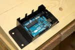
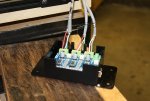
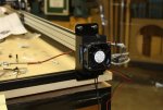
yeah, a bit on the chilly side around here, but got some more wiring done. spliced, soldered, and taped the spices to the stepper cable, then secured the arduino to the box, and got the x, y, and z axis wires attached. then added the cooling fan to the box, and secured the box to the frame of the machine. also secured the waste board to the bench as well. only a few more things, and then the testing begins. one other thing, i didn't follow the instructions about resistance testing to see which stepper cable went to which set of motors. i cheated and marked the ends of the cables, 1 mark for z, 2 marks for x, and 3 marks for y.
 

Attachments

  • 049 finished splice.jpg
    049 finished splice.jpg
    92.3 KB · Views: 9
  • 050 arduino in case.jpg
    050 arduino in case.jpg
    103.1 KB · Views: 8
  • 051 x y z axis wired in to controller.jpg
    051 x y z axis wired in to controller.jpg
    100.3 KB · Views: 8
  • 052 cooling fan added.jpg
    052 cooling fan added.jpg
    105.3 KB · Views: 8
  • 053 arduino assembly attached to frame.jpg
    053 arduino assembly attached to frame.jpg
    86 KB · Views: 9
Last edited:
... i didn't follow the instructions about resistance testing to see which stepper cable went to which set of motors. i cheated and marked the ends of the cables, 1 mark for z, 2 marks for x, and 3 marks for y.

Good progress, Dan! Like you, I marked my cables with a Sharpie to them identified until I finished attaching the panel connectors, then added a tie-wrap with a label tab to all of the wiring ends.
 
Top