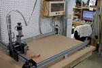
My CNC Build - Update

Nice, has to exciting to see it go. How deep of passes are you taking? What are the inches per minute cut and jog rates for the machine? (just curious)

Yep, it's good to see something made on it. I've been taking it easy so far on the cutting parameters. Since the little sign I posted is in cedar, I set the machine for 1/32" depth of cut and a total depth of 3/16". The default feed rate was 30in/min, but I reduced it to 20 in/min. Spindle speed was about 10,000rpm.
 
Oh, before I forget to mention it, I've had issues with SketchUcam and reported them to the powers that be on the Phlat Forum. The first thing I noticed was after installing SketchUcam, there were lines in some elements of my CNC bench drawing missing or changed. That was annoying enough, but the bigger issue is with the Phlat files installed SU2015 get Bug Splats randomly and regularly. The Phlat boys replicated the changing lines issue but haven't determined a fix. Until they publish some updates, I'm deleting all Phlat files on my PCs.
 
One thing I notice and lots of others experience also is that softwoods are move difficult to work than hardwoods.

Hardwoods just cut cleaner and give better definition and detail.

Tight grained woods like Maple are better than Oak or Ash.

In the CNC router world Chipload is a key factor.

Sometimes it is better to use lower RPM and higher feedrate to get bigger chips.

General rule of thumb is - depth of cut to be about 1/2 the tool diameter. In other words a 1/4 inch end mill can cut 1/8 inch deep.

GLAD - to see some cutting being done --- it's exciting for sure.
 
bill, i had that problem while running sketchucam in sketchup 8, going all white, but not crashing. one other problem i noticed, was that on 10 of the states, and some of the cars, sketchucam tried to create a new face. all of the files were made in the same way, but some got quirky while the others worked fine. mayhaps our resident sketchup guru has ideas on this?
 
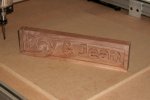
Toward the end of the day Wednesday, I set up a job to run the name plate below. There were random dimples in some of the edges - will see what the Inventables folks say about that.

zCNC_Easel_00a.jpg


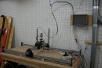
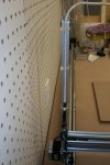
This morning, I've been cleaning up some of the wiring bundle and adding tie wraps to keep in in place. Here's what my cable routing looks like now - seems to work pretty good.

CNC_Bld_0017aa.jpgCNC_Bld_0017ab.jpg


I chose to make all of my wiring home run to the electronics, rather than mount terminal blocks on the motor panels.

CNC_Bld_0017d.jpg


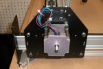
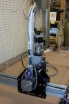
Since I'm running my wiring from above the system, I cut down a spare piece of 20mm by 20mm extrusion and mounted a piece on the gantry motor panel and the side axis motor panel to elevate the cabling.

CNC_Bld_0017b.jpgCNC_Bld_0017c.jpg


Now to finish the electronics housing.
 
Last edited:
I have the same basic machine but haven't really used it as other interests got n the way. And I find the cam to be tough for me to get all the little details down..

I have been trying Cambam Free and actually got a file that runs in Mach 4 but doesn't show the tool path. And the file won't run in Mach three even though the post processor was for mach 3..

The devil is in the details for sure.

I have used it as plotter quite a bit..

Garry

My Hello World Video is here..
https://www.youtube.com/watch?v=qTZ_JOQoN7I
 
Last edited:
Update 03/11/2015

Still moving along with the permanent wiring for my CNC as well as working on a couple of other projects.

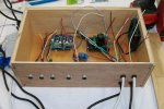
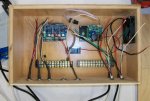
Today, I received some additional parts I needed and have done a bit more on the electronics box and cabling. The two photos below show most of the connectors in place along with some of the associated wiring. The five connectors on the bottom panel are for Z, Y and X axes, limit switches, and spindle power. On the right, the black cables are 100VAC in and out of the box; the white cables will carry low voltage DC (48, 24, 12 and 5) from the power supplies. The barrier strips will handle some of the I/O as well as the noise filter system for the limit switches.

CNC_Bld_0018a.jpgCNC_Bld_0018b.jpg


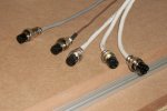
At the machine end, I added connectors to each of the cables to match the electronics box. The white cables are for motors on the X, Y and Z axes; brown is spindle power, gray is for limit switches.

CNC_Bld_0018c.jpg


With a little bit of luck, I should be back to more testing of the CNC operation. I've been working with Inkscape, MakerCAM a bit more and am getting comfortable with both interfaces. Of course, I'm getting impatient to have a go at some 3D but first things first, I suppose!
 
Update 03/12/2015

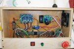
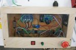
My main objective today was to clean up and terminate all of the wiring in the electronics box. As you can see, it looks a little better than yesterday! I added the small barrier strip on the left to serve as a breakout point for the 5V line from the gShield board, since it needs to serve the spindle relay and XYZ limit switches. In case you're wondering, I brought all grounds together using terminals on the long barrier strip on the lower right; the ground sides of all circuits are strapped together to help eliminate ground loop issues.

CNC_Bld_0019a.jpg


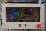
The lower part of the front panel holds the main power switch (big red button on the right) and controls for the spindle. The red rocker switch is an alternate spindle on/off switch to use when software doesn't add spindle control to the gcode; it simply parallels the spindle relay contacts. The knob is the spindle speed control.

CNC_Bld_0019b.jpg

I made the upper part of the front panel using clear acrylic in a simple frame of plywood. There are a few LEDs that flash when the machine is working and others that indicate whether a part is active. Also, having a clear front will give me a better view of which part is burning when I smell smoke.

Tomorrow, I'll finish wiring in the power supplies and give it a go!
 
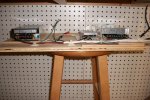
Well, everything went according to plan this morning. I finished the power supply wiring; cabling is ty-wrapped to the board and supplies are held in place now. No, the power supply board isn't going to live on my shop stool forever! I'll add a little shelf for it on the wall.

CNC_Bld_0020b.jpg


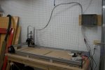
The power supplies are under the end of the CNC bench down the wall from the control box.

CNC_Bld_0020a.jpg


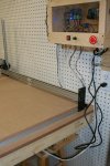
I still have a bit of cable management to clean up, but she's working away! In this shot, you can see the position of my CNC relative to my shop computer. Oh, and isn't that a nice shot of a dirty towel?

CNC_Bld_0020c.jpg


Not quite a Christmas tree, but it does have some pretty lights!

CNC_Bld_0020d.jpg


Now that I've got this project moving along well, it's time to produce something with it!!!

Thanks for coming along for the ride!
 
Last edited:
Thanks, Guys!

Darren, I've done a fair amount of wiring in my life, having been in engineering at a television station and cable TV. It's been a while since I did any soldering, so it took a few minutes to get my technique back, to say nothing of which reading glasses to use so I could see! :bonkers:
 
That's a really good looking setup.

Be interested to how you find your machine as some love them and others say they are to flimsy for anything. Personally I really like mine though I have done very little with it. Just drilled and tapped 90 holes in my spoil board with the aid of CA glue for hold down fixtures.

If you want to play with pretty's I highly recommend you try F Engrave as you can do engraving or v carving for free and it seems to work well.
http://www.scorchworks.com/Fengrave/fengrave.html
 
Top