getting really really really annoyed with photovcarve

Can I also ask which post-processor you're using to save the gcode. I got into looking at those recently for a laser setup, can verify there is nothing screwy with it if you want me to look at it as well.
 
Can I also ask which post-processor you're using to save the gcode. I got into looking at those recently for a laser setup, can verify there is nothing screwy with it if you want me to look at it as well.

Darren,

The recommended PP for both PVC and VCarve is GCode_Inch.pp. However, there is a difference between the files due to additional functionality in VCarve.

Neither of these versions has commands for starting and stopping a spindle or ending a program properly. I added those to the base GCode_inch, renamed it "SO2-09i_GCode_inch.pp" and placed an appropriate version in folders for VCarve and PVC. One modification I made to each of the base files is the gcode filename extension. The default is "nc" but I have my PPs make the extension "v.nc" for VCarve and "pvc.nc" for PVC so I can tell the difference in my gcode folder. Below is what I'm using to generate gcode. The two "VAR" lines I highlighted are the only difference in the commands in each file.

+================================================
+
+ G Code - Vectric machine output configuration file
+
+================================================
+
+ History
+
+ Who When What
+======== ========== ===========================
+ Tony 02/08/2005 Written
+================================================
+ Bill Arnold July 2015 Modified
+================================================

POST_NAME = "SO2-09GCode_inchVC"

FILE_EXTENSION = "v.nc"

UNITS = "INCHES"

+------------------------------------------------
+ Line terminating characters
+------------------------------------------------

LINE_ENDING = "[13][10]"

+------------------------------------------------
+ Block numbering
+------------------------------------------------

LINE_NUMBER_START = 0
LINE_NUMBER_INCREMENT = 10
LINE_NUMBER_MAXIMUM = 999999

+================================================
+
+ Formating for variables
+
+================================================

VAR LINE_NUMBER = [N|A|N|1.0]
VAR SPINDLE_SPEED = [S|A|S|1.0]
VAR FEED_RATE = [F|C|F|1.1]
VAR X_POSITION = [X|C|X|1.4]
VAR Y_POSITION = [Y|C|Y|1.4]
VAR Z_POSITION = [Z|C|Z|1.4]
VAR ARC_CENTRE_I_INC_POSITION = [I|A|I|1.4]
VAR ARC_CENTRE_J_INC_POSITION = [J|A|J|1.4]

VAR X_HOME_POSITION = [XH|A|X|1.4]
VAR Y_HOME_POSITION = [YH|A|Y|1.4]
VAR Z_HOME_POSITION = [ZH|A|Z|1.4]

+================================================
+
+ Block definitions for toolpath output
+
+================================================

+---------------------------------------------------
+ Commands output at the start of the file
+---------------------------------------------------

begin HEADER

"T1"
"G17"
"G20"
"G0[ZH]"
"G0[XH][YH]M3"

"(Toolname [TOOLNAME])"
"(Material Setup)"
"(X Min = [XMIN] Y Min = [YMIN] Z Min = [ZMIN])"
"(X Max = [XMAX] Y Max = [YMAX] Z Max = [ZMAX])"
"(X Length = [XLENGTH])"
"(Y Length = [YLENGTH])"
"(Z Length = [ZLENGTH])"

+---------------------------------------------------
+ Commands output for rapid moves
+---------------------------------------------------

begin RAPID_MOVE

"G0[X][Y][Z]"


+---------------------------------------------------
+ Commands output for the first feed rate move
+---------------------------------------------------

begin FIRST_FEED_MOVE

"G1[X][Y][Z][F]"


+---------------------------------------------------
+ Commands output for feed rate moves
+---------------------------------------------------

begin FEED_MOVE

"G1[X][Y][Z]"


+---------------------------------------------------
+ Commands output at the end of the file
+---------------------------------------------------

begin FOOTER

"G0[ZH]"
"G0[XH][YH]"
"M5"
"M30"
 
Last edited:
Bill,

I also customized my post.

I don't use line numbers - so I took that out. The machines don't need the line numbers.

I think I also trimmed out the trailing and leading zeros. It has been a few years since I edited my post, so I don't remember how I did it. For that matter, it could be another software post. But still, you can remove the line numbering. It makes the code a little easier to read.
 
now that things are back to somewhat normal around here (busy week), i'll get that file to you in the morning bill. i have since found that i could manually change the % of overlap for the bit, and have tried again. this time, it is a pic of the wife :blah:
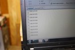
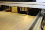
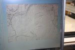
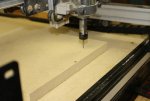
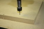
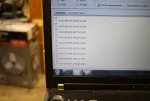
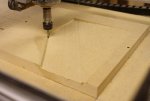
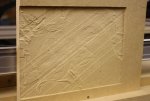
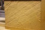
, and our grand niece aalana, taken at her birthday party (all of one now). in the following pics, there is one of the entire setup, a pic of what pvc said it should look like, and pics of what actually did happen. not sure why, since it started out ok, but it just kept getting deeper as the cutting went on (4hrs and 10 minutes of cutting), from just a shade over 1/16" to a bit over 1/4" deep, a bit odd, since the total limit on the depth of cut was 1/10". each time it went deeper, it left a distinct diagonal line. the bit that was used was a 1/8" ball nose bit, with a 10% spacing. not sure what went wrong here....
 

Attachments

  • 001 making sure all are zeroed out.jpg
    001 making sure all are zeroed out.jpg
    78.8 KB · Views: 12
  • 002 starting point.jpg
    002 starting point.jpg
    65.8 KB · Views: 10
  • 003 photovcarve image.jpg
    003 photovcarve image.jpg
    103.7 KB · Views: 11
  • 004 moving over to the right.jpg
    004 moving over to the right.jpg
    81.3 KB · Views: 11
  • 005 start of the cutting.jpg
    005 start of the cutting.jpg
    72.7 KB · Views: 12
  • 006 sample of gcode from deep area.jpg
    006 sample of gcode from deep area.jpg
    80.1 KB · Views: 9
  • 007 shallow to deep cut.jpg
    007 shallow to deep cut.jpg
    73.6 KB · Views: 14
  • 008 cutting parameters.jpg
    008 cutting parameters.jpg
    104.6 KB · Views: 10
  • 009 finished engraving.jpg
    009 finished engraving.jpg
    99.9 KB · Views: 14
  • 010 finished engraving with coat of shellac.jpg
    010 finished engraving with coat of shellac.jpg
    114.6 KB · Views: 18
Looks like you either lost steps on your Z, the cutter advanced out of the collet, or you have some backlash/looseness somewhere in the machine. My first suspects are physical, that's almost always where i find the cause of cuts like this.
 
hard to lose steps in the z axis, as it is a threaded rod. the bit did not advance as i always tighten the collet pretty good. as for the rest of the machine, it is as tight as a drum.
 
hard to lose steps in the z axis, as it is a threaded rod. the bit did not advance as i always tighten the collet pretty good. as for the rest of the machine, it is as tight as a drum.


Z can lose steps from the stepper or its driver getting hot or driver current not optimized.
 
Losing steps has nothing to do with the treaded rod.

Losing steps is what happens INSIDE the stepper motor.

Lost steps is when the computer is sending pulses (steps) and the motor does not turn, due to an obstruction or whatever. The computer believes the axis moved bu the number of steps - but the axis did NOT move those steps - hence - position is lost. With lost steps - the position will STAY lost - and not return until you re-home the machine. In your case - the lines you see are from something else, because the position changes and returns - again and again. If it was lost steps you would have milled a slot 1" deep through the entire part and possible into the table. !!! DAHIKT !!!

Even so - I don't think it's a losing steps issue. Lost steps is more dramatic than that.

You final results looks almost exactly like what I used to get on my machine every time I did anything 3D. Banged my head for a couple of years.

It always worked fine on 2D - but NOT on 3D.

I will try to post something I did that looks like your picture - you will see the similarities.

Same stuff - zero not returning, erratic surface - cutting in a ramped taper - pretty much what you have to a tee.

I don't have the issue any longer. That is in the past and totally gone.

My solution was to upgrade the BOB and upgrade to Mach3.

It was like magic.

I have never looked back.

I know you do not want to hear that.

That may or may not work for everyone, but it worked for me.
 
Looking at the last photo in your sequence, it looks like it could be an issue with lost steps or a loose collet.

For those not familiar with the way PVC cuts, it starts in the lower right and cuts on a diagonal that one can set in software until it finishes the cut in the upper left. Looking at the traces across the cut, the trend is that it gets deeper as the cut progresses. But there are also places where it appears to come back up a little.

As to upgrading, if you look at what people produce with systems like ours, save your money until you're ready to go into commercial production.
 
If it were lost steps you would not see a deeper groove then come back up then go deeper again - like the groove diagonally in the middle.

I think the problem is in how the electrical pulses are being processed.
 
talked with the shapeoko people, and dropped it in the lap of the vectric people again. now it is wait and see time again. one would think that if i were having this problem with this program, it should show up in cut2d when i use it, if it is a hardware problem, but it doesn't.
 
as to the collet, it seems that i do my jack armstrong, all american boy routine when i tighten it, even more fun when i go to loosen it. i'll have to get a side shot of the blank, because it seemed to go deeper, level out, then go deeper, and level out again. but i could be wrong.
 
as to the collet, it seems that i do my jack armstrong, all american boy routine when i tighten it, even more fun when i go to loosen it. ...

That can be problematic, Dan. Over-tightening a router collet can cause unnecessary stresses. My tightening process is to use wrenches to get it snug, then go about another 1/8 turn. I don't have loose bits.
 
talked with the shapeoko people, and dropped it in the lap of the vectric people again. now it is wait and see time again. one would think that if i were having this problem with this program, it should show up in cut2d when i use it, if it is a hardware problem, but it doesn't.

So, are you saying you can import the PVC vector file into Cut2D and it works right?
 
From what I have seen Shapeoko board has a lot of noise problems and they just want to ignore the problem in hopes it goes away. A friend of mine is have some of the same problems with his Shapeoko 3 every time he turns on the router it drops about 1/4" and the problem is noise. I am with Leo on this, go to Mach 3 and a new BoB and don't look back.
 
Top