- Messages
- 8,389
- Location
- Williamette Valley, Oregon
If there are any real metal workers here, please close this thread and move on, strictly amateur hour here 
So I'm doing another project and found that it sure would be handy to have a go/no go guage for lathe turning that was slightly more adjustable than a box wrench (that and my box wrenches kept getting lost in the sawdust). I had tried using calipers, but the pointy ends make that a no-go when the lathe is turning so they are slooow. After thinking about it for a while I decided to make one. Features desired were:
What I came up with is basically a set of sliding jaws made from some cold rolled steel form the borg.
Parts:
All told this cost me $15 and I have a lot of cold rolled and some washers left over.
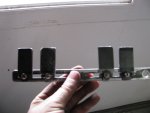
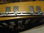
This is actually doing the second half of the body so you can see what the desired outcome is on the left here.
First scribe a line down the center of the piece you're going to use for the body. Doesn't have to be exactly on center, but moderately straight is desired.
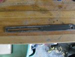
Then center punch a bunch of dots down the line and drill it out. I used a drill bit just slightly under the size of the machine bolt (like 1 step down from what you'd use if you were tapping it).
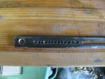
Once its drilled you can either use a small round file or a cold chisel to remove the bulk of the webbing between the holes. If you use a cold chisel leave webbing every so often like in this picture to keep the sides from spreading apart and then remove the remainder in a second pass being a little more gentle on it.
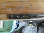
Then its file file file. I started filing with the side of the file to open up the remainder of the webbing.
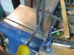
and then switched to filing flat. Your goal here is to get it pretty flat and straight and just barely wide enough that the machine bolt can barely fit and slide from one end to the other.

Now the body is done (the right side looks the same as the left side in the first picture) its time to make the jaws. First measure off about 2" from the 1" material, scribe and hacksaw it off. The length doesn't have to be exact, but they should all be close to the same.
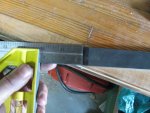
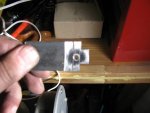
Now use the inside slot in the body to scribe the jaws. Line one side up with the end of the jaw and scribe. Then rotate 90 and line the body up roughly with the middle of the jaw and scribe again.
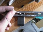
You should end up with a little square with lines coming off of it like below. The center punch the middle of the square.

Drill the spot you center punched out and then tap it to accept the machine bolt. Then hacksaw outside the lines like below to make the wings.
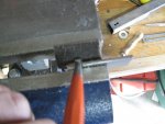
Now you need to bend the wings over a bit (basically so they stick out about 1/8" inch). The wings slide in the slot in the body so they eventually have to fit. Ideally at this point they are somewhat over sized. For bending the first wing over I just clamp it in the vice and use a punch and a hammer, the second one is tougher because the first is in the way so I clamped it around a piece of hardwood and repeated the process.
(continued next post)
So I'm doing another project and found that it sure would be handy to have a go/no go guage for lathe turning that was slightly more adjustable than a box wrench (that and my box wrenches kept getting lost in the sawdust). I had tried using calipers, but the pointy ends make that a no-go when the lathe is turning so they are slooow. After thinking about it for a while I decided to make one. Features desired were:
- multiple settings in one tool
- Easy to adjust
- can be used with the lathe on to part to size
What I came up with is basically a set of sliding jaws made from some cold rolled steel form the borg.
Parts:
- 1 piece of cold rolled steel about 8" long, 3/4" wide and 1/8" deep for the body
- 1 piece of cold rolled steel about 10" long, 1" wide (3/4 would work but 1" is easier) and 1/8" deep for the jaws
- 4 machine bolt, I used M8 about 1/2" long because thats what the borg had with matching wing nuts
- 4 wing nuts and washers to match the machine bolts
All told this cost me $15 and I have a lot of cold rolled and some washers left over.
This is actually doing the second half of the body so you can see what the desired outcome is on the left here.
First scribe a line down the center of the piece you're going to use for the body. Doesn't have to be exactly on center, but moderately straight is desired.

Then center punch a bunch of dots down the line and drill it out. I used a drill bit just slightly under the size of the machine bolt (like 1 step down from what you'd use if you were tapping it).

Once its drilled you can either use a small round file or a cold chisel to remove the bulk of the webbing between the holes. If you use a cold chisel leave webbing every so often like in this picture to keep the sides from spreading apart and then remove the remainder in a second pass being a little more gentle on it.

Then its file file file. I started filing with the side of the file to open up the remainder of the webbing.

and then switched to filing flat. Your goal here is to get it pretty flat and straight and just barely wide enough that the machine bolt can barely fit and slide from one end to the other.

Now the body is done (the right side looks the same as the left side in the first picture) its time to make the jaws. First measure off about 2" from the 1" material, scribe and hacksaw it off. The length doesn't have to be exact, but they should all be close to the same.

Now use the inside slot in the body to scribe the jaws. Line one side up with the end of the jaw and scribe. Then rotate 90 and line the body up roughly with the middle of the jaw and scribe again.

You should end up with a little square with lines coming off of it like below. The center punch the middle of the square.

Drill the spot you center punched out and then tap it to accept the machine bolt. Then hacksaw outside the lines like below to make the wings.

Now you need to bend the wings over a bit (basically so they stick out about 1/8" inch). The wings slide in the slot in the body so they eventually have to fit. Ideally at this point they are somewhat over sized. For bending the first wing over I just clamp it in the vice and use a punch and a hammer, the second one is tougher because the first is in the way so I clamped it around a piece of hardwood and repeated the process.

(continued next post)


