Even more Info


To give credit to the people that I got information from, here are the web sites.
http://www.bayouwoodturners.com/december2007/steelsnake.pdf
Capt Eddies plans
http://www.sawmillcreek.org/showthread.php?t=80501 Fred Morton's version
http://www.sawmillcreek.org/showthread.php?t=82387&highlight=Capt+Eddies+Ste William Bolen's version
I have combined ideas from the above versions and adapted some of my own ideas to create my version. I used bronze bushings purchased at the local farm store. They are 1/2” outside diameter and 3/8” inside diameter. They did fit snug in a standard 1/2” drill bit hole. The 1 x 1 solid steel stock was purchased from a local fabrication company and paid scrap iron price as it was a cut off.
I did do some design work on the unit on a cad program to work out how all the pieces would work on the lathe. Saved me some time in experimenting. I also made a wooden mock up first to see how the rig would move on the lathe.
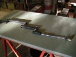
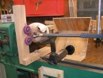
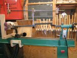
The tailstock mount is by a #2 morse taper that I made on my wood lathe by using a home made chuck, my little 4” grinder and a file. Took about 45 minutes to make. Drilled a 5/8” hole in the 1 x 1 steel stock and added a couple of 5/16” set screws to hold it in place. See photo of the tailstock assembly.
The half lap joint continues to give me some trouble as there is some lateral movement that I have not been able correct. The unit still works but does have some movement if you get to aggressive with the cut.
The front end is a 6” long piece of the 1x 1 stock with a 1/2" hole drilled 2” deep in from the end. Set screws hold it in place. I think this will allow me to use some other types of boring bars on the unit. The hexagon piece is something that I made to use with a scraper bit. It was an experiment and did not work like I wanted. I picked up that piece from a local fabrication company and paid scrap iron price as it was a cut off. The octagon shape I hope will allow me to turn the smoothing scraper that I use on the inside of forms to a shear scrape angle. Not sure if that is going to work.
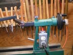
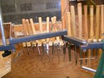
The photos attached to the previous posts should be self explanatory. There is also a pdf file attached of the cad drawing. you will have to rotate the pdf file to view. Not sure what I did wrong.
Hopefully, this is not too much information. If it is not, feel free to e-mail me or post the question.

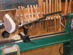
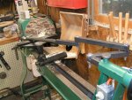
 I think you'll like that kind of hollower more than the captive "D" handle style.
