5' x 5' CNC Router Build

Motors arrived today.
2020-01-12 21.19.50.jpg

These are huge in comparison to my nema 23's on my old cnc, about 10lbs each. :eek:
2020-01-12 21.15.55.jpg 2020-01-12 21.18.01.jpg

I've got a Nema 34 to 23 adapter plate coming for the z-axis, but I think I may need some spacers yet, the coupling adds about 1/2" or so.
2020-01-12 21.15.07.jpg
 
Just make sure you can hold a 1/2 shank cutter - that is REALLY important.

Today I was at my clients shop helping him to optimize a program for a 3D whale that he sells. I had his machine cutting at over 400 IPM.
 
Just make sure you can hold a 1/2 shank cutter - that is REALLY important.

Today I was at my clients shop helping him to optimize a program for a 3D whale that he sells. I had his machine cutting at over 400 IPM.
The spindle is coming with a full set of E20 metic collets, but I've got a full set of imperial E20 collets, with a 1/2" size already.
Cutting at that speed is crazy fast compared to what I'm used to (20 - 30 ipm). I have cut at about 100 ipm, but was totally on accident, however the machine did fine luckily.
 
I've got most of the electronics now and have had a metal electrical enclosure that is about 18" x 18" x 4" I've held onto for years now as I thought I would use it for my cnc. I'm coming to the realization the it's about half the size I will need. So I started shopping around and larger enclosures are starting at about $250. :eek:

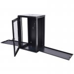
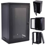
A while back I purchased a small server cabinet for my network stuff. I was working on a server earlier this week and realised one of the cabinet would work well and are only about $80 - $100. They've got a rack in both the front and back, and removable side panels to access equipment.
61GNhfBlqZL._SL1200_.jpg61PAVIGnYPL._SL1200_.jpg

I know they are not dust proof though, but I think I can reverse the exhaust fan and 3d print an adapter to mount a filter on. Then it could pressurise the cabinet with filtered air, keeping the dust out.

Should be enough space for the computer as well.
 
The white board will probably be some aluminum clad plywood I have on hand. The front and rear mounting racks on the cabinet above can be moved forward or reverse. I'll probably move the rear set forward and mount the plywood to it so that I can do some wire-routing from the back side to keep things clean and balance the weight in the cabinet as it may go on casters.
CncControlCabinet.jpg
The bottom 4 power supplies will be for the drivers, they are 70v each. I will share one of the two Y axis drivers with the A axis as both won't be moving the motors at the same time. The top one is a 24v Power supply for the board, I may also need a 5v power supply in there as well. I plan to run 220v to the cabinet, through the DIN breaker, and then distribute that to the power supplies and VFD.
 
The white board will probably be some aluminum clad plywood I have on hand. The front and rear mounting racks on the cabinet above can be moved forward or reverse. I'll probably move the rear set forward and mount the plywood to it so that I can do some wire-routing from the back side to keep things clean and balance the weight in the cabinet as it may go on casters.
View attachment 108946
The bottom 4 power supplies will be for the drivers, they are 70v each. I will share one of the two Y axis drivers with the A axis as both won't be moving the motors at the same time. The top one is a 24v Power supply for the board, I may also need a 5v power supply in there as well. I plan to run 220v to the cabinet, through the DIN breaker, and then distribute that to the power supplies and VFD.
Darren what are the dimensions of your panel, I am working on my layout also. I am planing on segregating the AC wiring and power from the signal. In my case it may be more of a problem because I am planning on using the external CNC control as opposed to the breakout board...
 
Darren what are the dimensions of you panel, I am working on my layout also. I am planing on segregating the AC wiring and power from the signal. In may case it may be more of a problem because I am planning on using the external CNC control as opposed to the breakout board...
That one is 19" wide, 24" tall. Though for the cabinet above, I could go to about 30" tall.
 
So I found an 18U cabinet for $3 more than the one above, so it's been ordered.
61ooR5PpaWL._SL1200_.jpg


It's 35" tall, so an extra 10" or so to layout things.

The spindle/VFD should come in tomorrow, so other than some wiring and odds/ends I'll have everything to make final design changes for. I'm planning to work on the control panel board and wiring things up over the next few weeks, then will start picking up steel when hopefully the weather is better. We are expecting an ice storm tonight/tomorrow.

I'll probably weld a support up the back of the cabinet to support a monitor. I also started setting up a new (used) pc with Mach3 tonight for this machine.
 
Last edited:
I've been plugging away on several aspects of this build this weekend.

I didn't get the correct mount on the zAxis, so I ordered a nema 34 to 23 adapter plate. However the shaft connector adds about 6mm to the shaft connection, so I drew up and printed a spacer.
2020-01-20 14.54.11.jpg 2020-01-20 14.54.15.jpg 2020-01-20 14.54.03.jpg
The spacer has rings on both sides to keep the shafts centered/aligned.
2020-01-20 14.54.35.jpg 2020-01-20 15.28.22.jpg

Next I'm printing rear covers for my motors that will allow me to mount some aviation connectors in them and help cap off the ends to keep dust out.
2020-01-20 16.48.44.jpg

I'm working on a new layout for the larger equipment cabinet I bought. My thought is to have the 220v come in at the bottom corner, then distribute that out to the power supplies and VFD. I'll also split out for a couple of 110v outlets. Since the cabinet has side panels that open, I've got high voltage on the left outside, cabling to the motors will come up the center, and low voltage/data will be on the right outside.
CncControlCabinet_34.png

I've picked up some wire channels to help keep the spaghetti to a minimum.
2020-01-20 16.49.51.jpg

Lastly I'm printing up some brackets to mount the power supplies with.
2020-01-20 16.48.25.jpg
 
Looks like one of the octopi's panic'd when I did a wifi update tonight, so the print stopped about 95% of the way through. Still allowed me to do a test fit to the motor.
2020-01-20 16.48.44.jpg 2020-01-20 21.04.41.jpg 2020-01-20 21.09.43.jpg 2020-01-20 21.09.54.jpg 2020-01-20 21.19.59.jpgB
I'll just print the last 5% and glue it on to this one, so no big loss. I've kicked off another two to print overnight and will print the rest tomorrow.

BTW, these are connected to the ends of the motors using the screw holes for the through bolts that hold the motors together use. There are about 3 or 4 thread that can be used to screw into for holding these on.
 
Top