Alan Bienlein
Member
- Messages
- 2,045
With all the discussion on dust collection systems lately I figured I would take John Lanciani up on his generous offer of borrowing his test equipment. He sent the following test equipment for me to take readings on my home built Pentz design cyclone.
Dwyer 471 hot wire anemometer, a UEI EM151 digital manometer, and a basic analog clamp-on ammeter but I substituted my Sperry digital clamp on amp meter.
My system is home built from plans on Bill Pentz's website. It is a 20" diameter cyclone with the Leeson 5 hp motor turning a 16" backward incline steel impeller. It has a 5" x 10" rectangular intake and exhaust into 2 seasoned Wynn 9L300 filters. I did not clean the filters before taking these measurements.
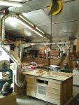
Here are a couple of photos of my setup. I put numbers on each drop to make it easy to follow exactly what part I am testing.
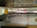
This picture shows where I connected the manometer and the hole circled in red is where I inserted the hot wire anemometer.

Here are the pictures with the corresponding numbers for the test. All measurements were taken in the 8" duct and opening and closing the blast gates on the various branches. Talking with John he said to divide the FPM by 2.85 to get the cfm.


Blastgate-----SP-----FPM------CFM------Amps---------Tool
All closed-----14.9"---700------245-------11.8---------None
All open-------3.6"---6250-----2192------18.5----------All
#1-----------10.9"---3400-----1192------16.5---------SCMS
#2-----------11.5"---3125-----1096------16.3--------8" jointer
#3-----------12.4"---2900 ----1017------15.6--------Ridgid TP1300 Planer
#4-----------6.21"---5600-----1964------17.9--------End of duct work
#5-----------10.2"---3600-----1263------16.9----------Table saw
#1 & #5------6.51"---5200-----1824------17.8--------Table saw & SCMS
#2 & #3-------8.3"---4300-----1508------17.4--------8" jointer & TP1300 Planer
These readings are with the machines connected like they are normally used. Number 4 is an end of duct run that I thought I might use one day to expand.
I do want to plot a graph of SP and CFM for my system but want to make sure I do it correctly so I don't waste my time repeating it so any help would be appreciated.
Dwyer 471 hot wire anemometer, a UEI EM151 digital manometer, and a basic analog clamp-on ammeter but I substituted my Sperry digital clamp on amp meter.
My system is home built from plans on Bill Pentz's website. It is a 20" diameter cyclone with the Leeson 5 hp motor turning a 16" backward incline steel impeller. It has a 5" x 10" rectangular intake and exhaust into 2 seasoned Wynn 9L300 filters. I did not clean the filters before taking these measurements.
Here are a couple of photos of my setup. I put numbers on each drop to make it easy to follow exactly what part I am testing.
This picture shows where I connected the manometer and the hole circled in red is where I inserted the hot wire anemometer.

Here are the pictures with the corresponding numbers for the test. All measurements were taken in the 8" duct and opening and closing the blast gates on the various branches. Talking with John he said to divide the FPM by 2.85 to get the cfm.


Blastgate-----SP-----FPM------CFM------Amps---------Tool
All closed-----14.9"---700------245-------11.8---------None
All open-------3.6"---6250-----2192------18.5----------All
#1-----------10.9"---3400-----1192------16.5---------SCMS
#2-----------11.5"---3125-----1096------16.3--------8" jointer
#3-----------12.4"---2900 ----1017------15.6--------Ridgid TP1300 Planer
#4-----------6.21"---5600-----1964------17.9--------End of duct work
#5-----------10.2"---3600-----1263------16.9----------Table saw
#1 & #5------6.51"---5200-----1824------17.8--------Table saw & SCMS
#2 & #3-------8.3"---4300-----1508------17.4--------8" jointer & TP1300 Planer
These readings are with the machines connected like they are normally used. Number 4 is an end of duct run that I thought I might use one day to expand.
I do want to plot a graph of SP and CFM for my system but want to make sure I do it correctly so I don't waste my time repeating it so any help would be appreciated.
