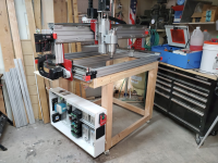
Reconfig of the Carol/Don/Brent CNC or as I like to call it, the Big CDB. Updated -> DONE!

IIRC the 220 went through the paddle switch bac to the panel then went to the small DC power supplies and to the main contactors after the main contactor it went to the spindle and to the stepper power supplied. The contactor was energised by the on off Push buttons on the front of the machine through a latching relay. does that make sense. if not I can draw a quick schematic.
Makes perfect sense. Thanks!
 
From a wiring standpoint, I agree with Don, makes sense to have the drivers closer to the patch panel on the left. Could also maybe just do the drivers over the PSs and move the lower voltage items to the right side.

You are just putting the noise filter between the din buss and the vfd, right? You don’t want the vfd sending noise back to the buss for all the other components to receive that noise.
 
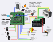
So I decided to change the controller board I'm going to use on the CDB. The one I was using I discovered was not easy to change the firmware and so I went back to the drawing board.

I discovered something called grblHAL, which is a pretty complete refactoring of grbl (8bit) to be used 32 bit boards.

The board I picked, grblHAL Breakout Board uses a 'Teensy 4.1' microcontroller as opposed to the old grbl/ramps boards that used an arduino controller. Don't let the name teensy fool you. This small little board has loads of pins and can support a 5 axis machine with all the bells and whistles.

It has a built in 0-10volt output for controlling a vfd and spindle.

It basically comes as a kit,with the surface mount components already soldered on. all I have to do is solder in the connectors and plug in a teensy.

I've already got the teensy and have got everything installed in order to be able to customize the firmware, but really, there's no need to do tha as they have a web based tool that will configure and generate the firmware hex file for you to load onto the teensy via a little utility.

The thing I like about this one is that it's got all the outputs I need, it's meant to be used with external stepper drivers, and has screw terminals for all the connections.

1680100469506.png
 
so it still needs a PC to run the program right ? It looks like it will get the job done. I like the fact that it has seperete input for each limit as opposed to the BOB that I used where they were all the same input. Does it run on standard "Fanuc G Codes" ?
It still runs standard gcode, and uses the vectric grbl post processors.

It can use a pc to run it, but that can also be a headless raspberry pi running cncjs.

It also has it's own web ui capabilities that I haven't thoroughly researched, but that would require one of the break out boards with an ethernet connection as it doesn't (yet that I know of?) support wifi directly.
 
The new controller sounds super interesting. I wish this was out when I was looking at controllers, $75 vs $350+ for what I got certainly would have been worth trying. I'm happy with what I got, and its worked well. If I decide to get away from mach3 I may have to bight the bullet and go with one of these. I look forward to your full review. ;)
 
IIRC the 220 went through the paddle switch bac to the panel then went to the small DC power supplies and to the main contactors after the main contactor it went to the spindle and to the stepper power supplied. The contactor was energised by the on off Push buttons on the front of the machine through a latching relay. does that make sense. if not I can draw a quick schematic.
Don, I'm trying to wrap my head around how to wire the contactor.

What I think I want to do is to wire it up like you had it where you press one button to engage it and one button to disengage it. I'm thinking I'd wire up the E-stop button to not only trigger the e-stop on the controller, but to disengage the contactor which would have the stepper and spindle power running through it.

All the diagrams I'm finding seem to show using mains current to have the contactor latch, but it seems like you were using the 12volt power to cause the contactor to engage with a couple other relays?

It would be a big help if you could either do a quick diagram or point me in the right direction to find a wiring diagram for that.

Thanks!
 
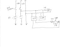
Brent the Paddle switch removes all power from the panel. Once it is closed the 12 Volt and 5 volt power supplies have power. I believe I used the 12 Volts to run to the start stop Push button the red being normally closed and the green being normally open One of the contacts on the 12 Volt relay pulls in the Main contactor. Here is a quick scketch. Forgive the chicken scratching.
CDB002.jpg
 
I think it's starting to make sense now. I think I might experiment with doing a test wiring up before I do all the wiring.

What I'm basically starting to understand is that the relays used are just replacing the momentary switches and are using the low voltage wires from the buttons to activate the mains power to close the contactor.

Thanks Don!
 
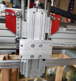
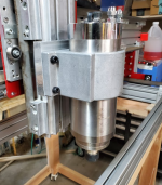
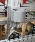
And the spindle mount adapter is finished. The more I thought about it, I thought I could probably just manually machine the adapter instead of taking a day or 2 of messing around with the ox to get it to cut aluminum.
The raw material, a bar of aluminum 6"x4"x.750"
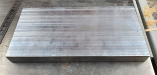
1680226838203.png

Now in order to determine where the holes are I took the spindle mount and put it on my scanner to get an image of the hole pattern. I pulled that into sketchup and used that image to make a drilling template with all the holes in the right places.
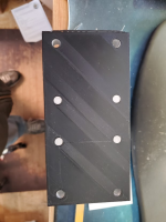
1680227175458.png

Once that matched up, I cut a little bit off the side of the bar to match the size of the mount. I redid the template to resize the holes to work with a vix bit self centering drill bit and glued the template to the aluminum bar.

I drilled some pilot holes with a 1/8" bit. For the holes that mount the spindle to the plate, I drilled the holes slightly undersize and tapped them with an M8x1.25 tap to match the bolts.

For the holes to mount the plate to the z axis, I drilled the holes so that the 8mm bolt would go through, and then took a slightly larger than 1/2" bit to countersink the hole for the cap screw. and here it is. Didn't take much more than an hour to drill and tap it all. Doing the templates and setup work took a longer, due to printing out the templates.
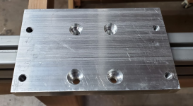
1680227403262.png

What do you know, a perfect fit. Even with the screws not fully tightened this does not wobble at all
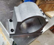
1680227574533.png

And it fits on the z axis right nice.
1680227694095.png1680227608801.png1680227659648.png

Couldn't be happier with how this turned out.
 
Did a few things today.

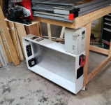
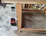
Worked on the mounting of the cabinet to the cart. Used some french cleats on the back to make it easy to mount/unmount. VFD will go on top at the front.
1680299518190.png

Paddle switch looks a little low, but there will be a control panel up higher with the cycle start, feed hold, and E-stop.
1680299613147.png

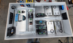
And did the layout of the electronics. USPS has decided to give the control board a bit of a delayed trip, so still waiting on that. It will fit in the area at the bottom left.

I've left a spot open in the upper middle for another stepper driver for the Z-axis, for when I get around to it.

Might have gone a little wild with the wire channels, but they should help to keep the wires nice and tidy.

1680299761186.png

Looks like I'm making some progress. Once the controller gets here, it's going to be a little bit of soldering and a lot of crimping end connectors and running wires.

I feel like I'm actually starting to make real progress.
 
Looks like a large distance from tool tip to the point where the spindle mount is attached to the "Z" axis. That just leaves room for flex (lack of rigidity)

Mine is similar.
I bought an additional spindle mount bracket.
That's one of the upgrades I plan to do on my machine to increase rigidity
It is noticable when cutting metals like Aluminum Copper and Brass.
STUBBY is best

I also bought Centroid Acorn BOB and software plus a few other goodies
I will move away from Mach3 software - and replace the Mach BOB and Chinese USB interface

I also need to replace my "X" axis Rack and Pinion.
I have a measurable amount of wear.
I have compensated with backlast comp.

Some of these things show up when making small very precise things.

On the GRBL, read some of the posts on Vectric Forums
There are some indiosyncresis with the sender.
I really don't know anything about it, except from some of the posts on Vectric.
 
Looks like a large distance from tool tip to the point where the spindle mount is attached to the "Z" axis. That just leaves room for flex (lack of rigidity)

I can easily move the bracket down loader on the Z-axis to grab the spindle lower. That sounds like some good advice.

I'm wondering what you might use to lubricate the rack and pinion? I need to do some work on making sure all the wheels and every is adjusted nice and tight.

Theres a specific version of software made to work with grblHAL called IOSender that accounts for some of the differences between old grbl and this newer version, particularly with the setup and configuration.

That centroid stuff looks pretty nice!

I'll check it out on the vectric forums.

Thanks Leo!
 
I use a dry moly lube on the rack and pinion.

I think the machine is worthy of the Centroid.
I had finished a nice job and that allowed to enough money to do the upgrade.

I want to be able to probe a surface and create a point cloud surface.
I bought the probe and a tool touch sensor.
I like that Centroid is USA with lots of support.

You are gonna be happy with just how robust your machine will be.

Is your spindle ER-20?
You cab use 1/2 shank cutters?

I can spin and cut with a 3-1/2 panel raiser cutter.
I think I loaded a video of that.
 
Top