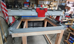
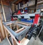
Reconfig of the Carol/Don/Brent CNC or as I like to call it, the Big CDB. Updated -> DONE!

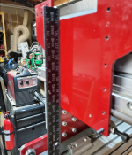
Well, Haven't shown much progress the last few days, but I've been working on it. Found some things that must have come loose on the trip up to reno, so I've kind of taken it all apart to just add a little loctite to some things and make sure everything was tight and square.

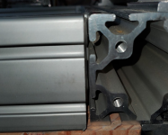
For example, some of the corners opened up and were not quite tight to each other.
1679175954432.png
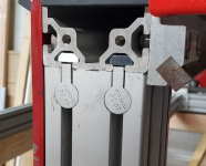
The Gantry wasn't sitting quite tight on the risers, and I noticed there are a couple of little anchor fittings that must have gone missing before Don got the machine.
1679176044817.png

Like Don, Once I got things back assembled I was finding that there was a tilt to the gantry that was driving me crazy. I tried several times to correct it, but found that part of my problem was checking it with a not so square 'square'. So I went to the pile of squares until I could find one that was closest to square.
1679176211228.png

I then took a suggestion Darren had made about using a laser level to make sure the bed was coplanar. I loosend up the corner bolts, put the laser on a support and used a little block of wood, a pencil and shims to make sure the bed was flat and level and then tightened everything down again.
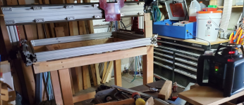
1679176300652.png

And success, It ended up being perpendicular on both ends without a whole lot of messing arounds.
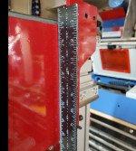
1679176394556.png1679176415101.png

I also decided that if I do want to do a rotary, I'll do it along the X axis end of the machine, which gives me 4' of room instead of the Y, which would only give me 2' of room.

I ordered a new crossbar and some other fittings in order to make that happen.

While I wait for all that, I think I'll get started on the Electrical components next.
 
At 2450Kg per caster it is a bit overkill isn’t it? Even if they were 245Kg. :huh: Maybe you took the saying “in case of doubt build it stout” too far;)
They are 2450 newtons, which translates to about 250 kilograms or a bit over 550 pounds each. I have similar ones on my 750 pound lathe, and they're rated at 550 pounds each. These should do great under the Big CDB. :thumb:
 
Last edited:
Still plugging away slowly. The shop is still mostly usable. I'm really trying to develop the habit of using a tool then putting it away and trying to keep things in order.

Needless to say, I've still got a lot of room for improvement.


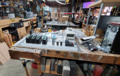
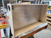
Today I laminated some sheet aluminum onto some ply to use as the backplate for the electronics enclosure.
Right now I'm playing a game of laying things out on the backplate to see how I might want to organize the electronics before I make cut the sides and box it up.

1679265952961.png

Trying to decide if I want to put the VFD Inside or not. The cool thing about the vfd is the control panel is removeable and can be placed remotely by using what appears to be a network jack. Need to do a little more research on that.

but it appears everything should be able to fit either way.

1679266130434.png

Next up will be to put some aviation connectors on the steppers and some end caps for them. Doing it because it's what Darren did, lol and I like stepper motors with removeable wires.

1679266265405.png
 
Brent, I kept the spindle away from the rest of the controls to lesson the chances of rf interference from the inverter. If you put the inverter in the same enclosure you might want to consider some rf filters.
That makes sense. I do have some RF filters I'm going to use. I'd originally thought I would put it outside, so I think I 'll continue to do that. Thanks!
 
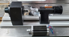
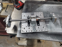
Well, Guess I'm going to have to take a pause and figure out how I'm going to mount my rotary access. Darren talked me into getting the same sort of mini lathe parts he got for making his.
It just kind of makes sense to do it now, rather than later.

I had a good sized Nema 23 stepper in in stock that should be just fine for this. The extrusions are just for demonstration only, as they would not be long enough to give me a full length across the front of the machine.

Didn't really make much of any other progress today as I ended up running to town this morning and helping my buddy do some wiring on his motorcycle this afternoon.

1679362665586.png
 
Decided that my current focus should be getting the bones of the machine ready for everything, so started going through it in detail. I feel like I should be making faster progress, but had a couple distractions and we got more snow today. Finding I can stand working out there in 40 degrees 'ok', but need to take some warm up breaks.

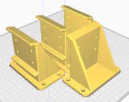
Spent the morning drawing up and working some cable chain supports. Went through a couple iterations, finally landed on this.
1679449601837.png

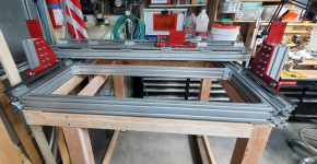
I got the new middle extrusion today so installed that and started going through the machine bolt by bolt. Found a few loose things here and there so took it apart a bit and just started torqueing things down to make sure everything was nice and tight.
1679449458997.png

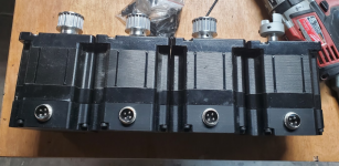
Cut the pigtails off the steppers and installed some aircraft connectors.
1679449422868.png
 
Sometimes I forget how long a journey this CNC has been on. Carol got the bones delivered in June of 2015. Reading through some of the old threads gives me some more insight into the history of this machine.

That being said, I did discover some issues with the z axis once I had the stepper off it. I tried to rotate the ball screw, and it was stuck. I took it all apart and discovered the grease on it had hardened into a sticky mess. I went ahead and used some wd-40 to clean it all up. From what I could find on the internet, white lithium grease seems to be recommended, so I had a can of the spray stuff and I lubed it up good and used my drill to run it up and down a bit to get everything running all smooth.
1679623608551.png

Z axis must have taken a bit of a digger at some point, lol. It's really mostly cosmetic and isn't isn't affecting anything much. I might take it to the anvil and see if I can flatten it, but Not sure I care enough to take things apart again.
1679623691715.png

I then spent some time tuning up the roller bearings and everything. Without the steppers engaged, I can move the x and y with one hand in a circle fairly easily. So easy, that I started to get worried I might roll the gantry off the rails, so made up some end stops. Printing out some tpu soft parts to help with the potential impact.
1679623906999.png1679623934209.png

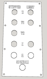
Started to work on the electronics enclosure a bit. Need to get the outside interface pieces figured out so I can box it in and do the wiring.
1679624047414.png

Designing a plate for the Jacks.
1679624567264.png

So, Basically,
1) Mechanically sound and all the bits have been adjusted to run smooth.
2) Getting the enclosure ready to install the electronics.
3) Running 3d printer to make stuff for the bumpers and cable management.

Feel like I'm getting a bit closer.
 
Last edited:
Z axis must have taken a bit of a digger at some point, lol.
yea, The folks who packed the stuff when Carol moved from Kalifornia were not too bright. Her oscillating spindle sander was stored upside down and all of the oil in the gear box leaked out also. Many thing got damaged in the move. I didn't have the heart to tell Carol. This is gonna be a nice machine once your done I may have to make a trip up to see it when it's done.
 
yea, The folks who packed the stuff when Carol moved from Kalifornia were not too bright. Her oscillating spindle sander was stored upside down and all of the oil in the gear box leaked out also. Many thing got damaged in the move. I didn't have the heart to tell Carol. This is gonna be a nice machine once your done I may have to make a trip up to see it when it's done.
Ooof. Yeah, I can imagine. Tough to get Hired help to probably care about this kind of stuff when all they think is 'heavy'.

You're always welcome!
 
Feel like I'm starting to see a light way out there at the end of the tunnel.

Did some work on the enclosure today, basically cutting access holes in it and slapping a little paint on it. Nothing to show, waiting for paint to dry.

There were some anchor connectors that were missing, so I ordered up some replacements. These were installed less than 5 minutes after the UPS guy handed them to me, lol.

1679708070780.png

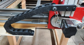
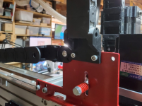
Also got the cable chains figured out today. Still printing out mounting brackets for the X and Z axis, but the Y is pretty much done.
1679708287970.png

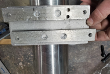
Was looking at the spindle mount and kind of got to thinking maybe I could do a little better. In for a penny, in for a pound I guess. Really glad I'm going through this level of detail, because I think I'll have a much better understanding of the machine going forward.

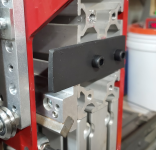
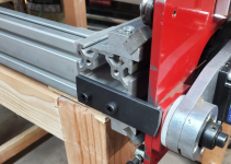
At any rate, A couple of bars of aluminum is what had been used, which I'm sure was pefectly fine.
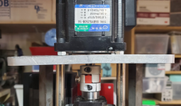
1679708583691.png

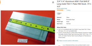
But I figured why not order a little aluminum plate for 26$ and see if I can improve upon it a little bit.
1679708629423.png

I'm doing a bit better with putting tools away as I use them or after the end of the day, so theres that. Kind of feel like I'm on the right path now.

Still running the 3d printers a lot for parts.
 
1679775418316.png

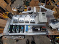
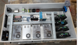
Ok, Audience participation time. Looking for critiques of this layout.
Power enters from the top left, L1 and L2 go through the white/green breaker, then through the paddle switch on the top right and then to the red and black din blocks.
The multi colored block is for the neutral, and the ground goes to the yellow/green one next to the breaker. That one connects the ground to the ground plane aluminum back of the enclosure.
I may add some additional ground din terminals, but the thinking is that the power supplies and such will pick up the ground from the ground plane.

Cooling air comes in from the lower left and I'll cut out an exhaust port on the top right under the paddle switch.

Next line is the controller, the pwm to 10 volt adapter for the spindle control, some contactors, and then 24v, 12v, and 5v power supplies.

At the bottom we have the power supplies for the steppers, and stepper controllers on the right.

I'm thinking the big contactor might be used for shuttind down power to the spindle and the stepper power supplies.

The other ones might be used for controlling the coolant pump, the shop vac, etc.

The controller uses 24v, the pi uses 5v, the 12volt might be used for some leds inside the case or on the machine itself.

That's my thinking so far.
 
Brent, my feeling is that the power supplies should be slid over all the way to the right and the stepper on the left side so they are close to the Pi board and the output from the steppers are as close as possible to what I assume it where the outputs for them are, close to the black plate on the left in that way the 220 power is not run close to the signal from the pi to the stepper. I would also revers where the power supplies are and the relay again to keep the 12 V and 5 VDC away from the power.
 
Makes a lot of sense. I'm thinking the power supplies probably generate more heat, so put them closer to where the heat will go out of the case too.

Don, What did you use the contactor for? All the power or just the spindle steppers? And what were the other little relay/contactors for?
 
IIRC the 220 went through the paddle switch bac to the panel then went to the small DC power supplies and to the main contactors after the main contactor it went to the spindle and to the stepper power supplied. The contactor was energised by the on off Push buttons on the front of the machine through a latching relay. does that make sense. if not I can draw a quick schematic.
 
Top