Sketchup and drawing Threads (Question for Dave Richards)

Brent Dowell

Administrator
Staff member
Messages
16,579
Location
Reno NV
Hey Dave,

So, You mentioned in the other post that I should post when I found something I couldnt do in Sketchup 2017.

I'd like to be able to model threads for using in 3d printed models.

The only 2 I've found in the extension warehouse are
EP Fasteners & Threaded Holes
Draw Whorl

Unfortunately, both of these say they are incompatible with 2017.

Do you know of any tools for drawing threadeds that might be compatible?
 
Hi Brent,

Both of those extensions do actually work with SU2017 despite what is shown in the Extension Warehouse. I think you can just consider the author's haven't done anything to them for a long time. That said, if you want proper standard threads that will work with machine screws or bolts, it's probably just as well you avoid those extensions. Neither one actually creates good threads. When I draw screw threads I use the Helix tool in the Curve Maker extension to create a path for extruding the thread profile and another extension called Eneroth Upright Extruder to do the extruding. Both are in the Extension Warehouse. A couple of other extensions that are very useful is Eneroth Auto-Weld and Bool Tools 2 which aren't free but well worth the small price.

What kind of threads are you after and what size? I'll make up a tutorial for you.
 
My current method of doing threads is to just undersize the hole and forze the bolt/screw in, but I'd really like to have threads in there, which is very doable with 3d printing, depending on the thread size and nozzle size used.

One of my latest projects was creating something that would attach to microphone stands.
There are 2 sizes for those.
3/8-16
5/8-27
I also do a fair amount of 1/4"-20 and assorted metric threads.

A tutorial on any one of those would be very helpful.

Thanks Dave!
 
Let's see if this helps.

Start by setting the units to Meters. I use meters for all 3D printing projects. The exported .stl file, by definition, is unitless. If you are modeling with imperial dimensions, you'll tell the slicer that the units are inches when you import the file.
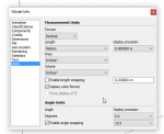
Screenshot - 11_24_2019 , 2_15_37 PM.png

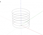
To create the path for the screw, use the Helix tool from Curve Maker. I'm modeling 3/8-16 threads here. I've set it up for more turns that I need for the moment. I'll actually be able to extend the screw threads later.
Screenshot - 11_24_2019 , 2_35_09 PM.png

And end up with this.
Screenshot - 11_24_2019 , 2_35_40 PM.png

Now on to the thread profile. I'm modeling for internal threads and for this using info gleaned from here. Note that I don't run the profile to the center. This helps to prevent some problems later.
Screenshot - 11_24_2019 , 3_16_29 PM.jpg

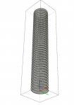
The helix was created as a group. The group needs to be exploded next. Then I used Upright Extruder to extrude the profile. Follow Me won't work for this. Be patient. This can take a little while due to the geometry being created. After the extrusion is completed, select it all and make a component. I set things up so the valley in the profile is centered on the end of the path. Once the geometry of the screw is there, the path can be deleted.
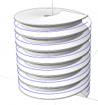
Screenshot - 11_24_2019 , 3_17_34 PM.png

Next prepare to cut the ends off the screw so it's flat at the ends. I draw a rectangle outside of the component and copy it up by some multiple of the threads.
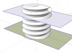
Screenshot - 11_24_2019 , 3_20_36 PM.jpg

I also edit the component to select there central geometry and delete it.
Screenshot - 11_24_2019 , 3_49_13 PM.jpg

Then cut the rectangles to the clipboard (Ctrl+X, Command-X) and then open the component for editing and use Edit>Paste in place to paste the rectangles in with the rest of the geometry.
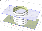
Screenshot - 11_24_2019 , 3_50_24 PM.png

Select all of the geometry, right click on it and choose Intersect>with Selected. Check closely to see that all intersecting edges have been created. When you select surfaces in between the cutting faces the selection should not continue beyond the cutting faces. In the following images you can see that isn't the case with all the thread surfaces. Just zoom in closely and add any missing edges with the Line tool.
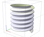
Screenshot - 11_24_2019 , 3_53_22 PM.png

Erase the unneeded geometry leaving a section of threads.
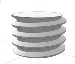
Screenshot - 11_24_2019 , 3_58_13 PM.jpg

Erase the faces on the ends and then copy the section to make it a bit longer than you need. As this is the internal threads you would use add this into your model and intersect the geometry before erasing the unneeded bits. Also make sure to correct the face orientation so that it will print correctly. Final image in next post.
 
I thought I should add the following in case it isn't obvious.

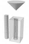
Once you've gone through the process of making the threads, create a component of it and save it in a local collection. You could have a library of internal thread components that you keep for later use. I would set the component's axes so the origin is on the center line of the thread component as the component's origin is its insertion point.

Screenshot - 11_25_2019 , 7_12_55 AM.jpg

Make the threads plenty long although you can always edit the component and add length if you need to do so.

You might also create a chamfering component to ease the lead-in on the threads. I just used Follow Me with a triangle to create a cone for that.

Screenshot - 11_25_2019 , 7_09_25 AM.jpg

If you make sure all the components are solids, you could use BoolTools 2 to do the trimming/subtracting when cutting the threads and stuff. The extension costs $20 but that's a small price for the time and potential frustration it could save. https://mindsightstudios.com/booltools-2/

If you need a hand with figuring out how to save the components for later use, let me know.
 
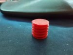
Well, Gave it a shot. My dimensions were way off and I had to scale it down to print, but just testing out the methodology.

I have a feeling I'm going to have a much better understanding of how screws are actually engineered after this.

Moving on to internal threads.

threadtest.jpg
 
Hi Bill,

I'll see what I can do.

Good start Brent. Does your slicer software allow you to enter the dimension units when you import the .stl file? The ones I've used ask for the units on import so there's no need to scale the model down before exporting the .stl.

I've found that modeling things I don't normally deal with in detail makes me learn how they are engineered. I found that years ago while making an animation in SketchUp to show how a sewing machine makes a lock stitch and recently with the spinning wheels I've modeled, I learned how they work.
 
I think I see what was going on that was very important.

You specified to use 'meters' in the model info, but were entering the units in the curve generator in inches.

I've read that's a fairly common thing to do, as it gets around a lot of the 'too small for that number of segment' type issues when modeling things in their normal unit, i.e. inch or mm.

I do see on the STL Export options that I can specify the export unit. I usually work in mm, and export in mm. I use Simplify 3d as my slicer and it takes it in as mm if I export as mm. Sometimes if it things something is really small, it will prompt to use a different unit.
 
I think I see what was going on that was very important.

You specified to use 'meters' in the model info, but were entering the units in the curve generator in inches.

Yes. Units to meters but pretend you are working in inches or millimeters.

I've read that's a fairly common thing to do, as it gets around a lot of the 'too small for that number of segment' type issues when modeling things in their normal unit, i.e. inch or mm.

Zackly!

I do see on the STL Export options that I can specify the export unit. I usually work in mm, and export in mm. I use Simplify 3d as my slicer and it takes it in as mm if I export as mm. Sometimes if it things something is really small, it will prompt to use a different unit.

But the .stl file type is unitless. Check to see if Simplify 3D gives you a setting for units on import.
 
I can't read the small dimension text but I think so. One thing, though. If you get the the length of the line at the bottom of (minor diameter) and center that on the height of the thread, the 30° angle will take care of the dimensions out at the major diameter.
 
Oh yeah, That image did get resized pretty bad.

So, Been practicing with this a bunch to day, but the part I seem to be having the most problems with now is the slicing of the top and bottom off. Seems like it's not generating a complete intersection and Like you mentioned I have to go in and try to figure out what lines need to be added in order to complete some of the faces.

Are there any tips on how to make that a little easier? Maybe blow it up even larger in size ?
 
Top