Submarine half Hull - USS Nathan Hale SSBN 623

Don Baer

Moderator
Staff member
I have always wanted a model of the submarine I served on. It was part of the original 41 Fleet ballistic missile submarines known as the "41 for Freedom". They were named after Freedom fighters. The first one was the George Washington. As the submarines were built they kept improving the designs. The major design changes happened 5 different times and each time they changed it they designated the design as a different "class" of Submarine. I was on the Nathan Hale which was the 3rd "class" of submarine. the George Washington was 382 Feet long and had a displacement of 6700 tons. The Nathan Hale the boat I was on was 427 feet long and displaced 8000 tons. While I could find a plastic model of the George Washington I have been unable to find a model of the class of submarine I was on so I decided to build one. This thread will be about the process I am using to build this one. By doing research in the Navel archives I have been able to get some basic dimension. Then by getting various picture I have developed a drawing scaling the drawing from the dimension that I could get. My model will be 24 inches lone so the scale is 1" = 17.7 feet.
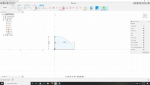
Below is the basic outline that I have worked up. All the design will be done in Fusion 360

1591467824541.png
 
Last edited:
one of the many challenges I have faced with doing this model is how to do the bow and the dunce cap (stern) of the submarine. once I figured it out it was one of those "ahhhh" moments and turn out to be very simple.
Fist I took picked a spot on the hull and looked up the diameter of the humm at that point then I drew a line from my reference point to a distance equal to 1/2 the hull diameter in the Y direction. Next I drew a line from my reference point to a distance equal to the distance from that section of the hull to the tip of the bow.
1591725056252.png
Next I drew an arc from the two end point of the lines in the X and Y Planes.
1591725184879.png

I then finished this part of the sketch and from the create menu I selected "revolve" from the menu. I then selected the axis to revolve around and told it to revolve the shape for 180 degrees since I only want half of the cone shape.
1591725454544.png

If I were doing a 3 D print I could also specify the wall thickness.
 

Attachments

  • 1591725413709.png
    1591725413709.png
    89.7 KB · Views: 1
I know the title states half hull, BUT, would you consider a full 3D on a rotary - or 2, 4, 6 fixture positioning?
If I had a rotary axis this same technique could be used, but for now this will remain a 3 D profile for two very good reasons. One I am still a novice at CNC and second I don't have a rotary axis, yet.
I guess without a rotary axis i could mirror the model and glue the halves together :unsure: ...lol:ROFLMAO:
 
You don't need a rotary to do it.

One big block of wood, big enough for the entire sub. Position one will do the half hull in one half of the block.
Flip the block over 180 and do the other half hull.

Another way is 4 positions @ 90 degrees

Another way is 6 positions, 4 @ 90 then position for each end.

Lots of ways to skin a cat.
 
1592074006330.png

34 different sketchs
11 different bodies
14 different planes
in full 3 D
I'll play a little bit with the outline, I am not satisfied with the bow section around the 7th segment but that's no big deal and I still meed to do a separate drawing for the fair water and stern plans(the aileron looking things that control the angle and the depth of the boat). They will be cut separate and attached to the boat. I need to order a couple of longer ball end mills to do the profileing the ones I have are to short to reach in the full depth. Also I need to get over to my wood supplier and see what he has that I can use to make this thing. Last time I was in there he had some 6/4 Bass wood that may do the trick.
 
I finish up the design this week.

ssbn 623.jpg
and I ran the cad program here is a shot of the tools path being generated.

Tool Path.jpg
this was done with a 2 mm ball nose end mill. It took 26 1/2 minutes o generate the program.
The G code file is 3,276 kb and according to the simulator it will take 7 hours and 5 minutes to run.
I was gonna run it this week end but looking at the program I may want to re think a few things to try t cut down on the time. I don't know if I want to run the machine for 7 hours non stop in a 100 degree plus shop.
 
Looks good.

So are you running a clearance pass with a larger end mill to hog off some of the waste? For that size I'd think you could run it in about 2 hours or so total. I typically put the 1/8" ball mill running about 50 ipm, but will bump up the speed/feed in mach3 to 80 - 100 depending on how it looks and sounds. Every machine is a bit different and will depend on the chip load of the bit, but I personally feel that 7 hours is a long time for that size.
 
I personally feel that 7 hours is a long time for that size.

I think it's due to several things. The only ball end mills I have are the 2 mm so I'll order in some larger ones. I'll do some playing with the program and try it with various size mill . I ran the same parameters at double the scale (1/2 the size of the model, 13.11" rather than 26.22 ) and it came out to 2 hours. I'll play with it and I may have to wait to run it till I get some bigger mills.
 
well by reducing the scale to 3/4 and doing it in 2 operations the first a rough shaping with a 1/8 ball mill and the final with a 2 mm. I can get the 1/2 hull done in 1 hour and 10 minutes. That sound reasonable so I think I'll run it and see how it comes out. First hot to head over to the gym and then stop by the pharmacy while I'm out to pick up a scrip
 
Top