The New Carol CNC.... design.

Don Baer

Moderator
Staff member
Well taking all the extrusions that we unloaded from the trailer I was able to come up with design. Pardone my poor drawing my sketchup skills are a bit rusty and I am still learning the newest version. The first phase will be to build the base so I have a place to assemble the machine. Keep in mind I am doing this in a 10x20 garage and there's a lot of junk (not mine) stored there. This used to be my shop but somehow I have lost floor space so I will have to reclaim it a piece at a time. Anyhow here is a drawing of the machine as seen from the front. The wheels will be locking.

NEW CNC.jpg


The back has a 10" deep space where I plan on housing all of the controls, power supplies etc. No worried about a layout yet but there will be an opening near the top on the cover/door and fans to circulate the air. Still up in the air if I want to enclose the bottom or just cover it with a screen to keep any critter out. heat is a killer on electronics and that one thing we get an abundance of here in Arizona.

Back of new CNC.jpg
 
looking at Carols posts it appear that this is all the pieces she had. The following shows the usable build area...unless I am missing something I see no way this machine could have done any more. I do thinks she was going to use the open space on the left for her rotary access but that would cut down on the usable work area...OH well..... it is what it is..

CNC work area.jpg
 
The gantry is on wrong, flip it 180, put the spindle on the other side, and you'll gain some work area. ;)

Edit: looks like that may be the way it's intended to mount if it's their pro version. Most others do mount on the opposite side. I know she was planning to have a 4th axis, which I thought was going on the right side of the first photo in your other thread.
 
Last edited:
Interesting that the gantry is going the long way? Would be stiffer if the gantry was going across the shorter dimension, or am I missing something?
 
for a cnc set up that is about the same size as mine (32x52 inches), it looks like that gantry was way overbuilt. i don't see too much of a problem with flexing, as the gantry beam has to be at least 60 mm x 40 mm, and with a 4 hp spindle, was she planning on going into ship building?
 
The gantry is on wrong, flip it 180, put the spindle on the other side, and you'll gain some work area. ;)

Edit: looks like that may be the way it's intended to mount if it's their pro version. Most others do mount on the opposite side. I know she was planning to have a 4th axis, which I thought was going on the right side of the first photo in your other thread.

The rack for the Y axis is only long enough (26" of rack) to allow 24" of travel and the way the Carriage is for the Z if the gantry were flipped I think it would hit the risers for the gantry and then I would loose travel in the X direction. I am pretty sure this is how it is supposed to be. I'll have to see when I get the base built and assemble the machine.
 
well one decision has been made for me thanks to Carol. I looked into what it would take to convert the rack and pinion drive parts that Carols bought to Nema 23 and it will cost over $53.70 per axis for new pulleys and timing belts so I'll just sink the $161 in to cost of Nema 34 motors for X Y and use Nema 23 on the Z like Carol planned. Going to be over kill for my intentions but hey the cost difference it just doesn't make sense to do other wise. The Nema 34 motors go though a 2.2:1 belt reduction so I'll have plenty of torque to move that big ole gantry around at 1000 IPM.
 
Now all you have to do is add some longer rails and extend those xy racks to take advantage of all that power. Then you'll have a beast. Aren't extrusions relatively cheap?
 
Looks good Don. I assume you're going to run 110v? What voltage are the power supplies outputting?
Yes 110 Volt that is one of the reason why I am selling the spindle drive system, I don't want to have to run the machine on 220. The power supplies are 60 volts output, they I am going by the recommendation of the Stepperonline site.
 
Dad, Larry and I saw this machine in mid-completion at Carol's Maker Space during a visit. I was just wondering yesterday . . . what happened to it. Glad it found a home.
 
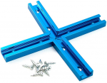
finishing up the design of the design so I can start ordering parts and am working on the work area and hold downs. Unlike Carol's original plan I an abandoning the vacuum table idea and going to a much simpler T track hold down, While sourcing T Track I ran across this handy piece of track I hadn't seen before and figured I would pass it along..
1580406831313.png

https://www.amazon.com/dp/B07H7CZB55/ref=psdc_552488_t4_B00EZON1FI
 
Nice. So are you thinking of doing an X style of hold down system? I know @Jason Beam did a similar hold down on his. I haven't decide yet what I'm going with. I did raise the bed on mine with the intention of having room for a vacuum system, but I've not done any research on it.
 
Top