Mike Stafford
Member
- Messages
- 2,352
- Location
- Coastal plain of North Carolina
I received a wonderful gift for my birthday with which I have had so much fun, a ROKR Vitascope. What the heck is a Vitascope you ask? It is basically a movie projector. This Vitascope is built from laser cut plywood and assembled like a 3D puzzle. The biggest surprise is that when it is done it will actually show a movie. It includes a film strip of a Charlie Chaplin cartoon as part of the kit.
I thought I would share my experiences with this kit with pictures and descriptions. If you guys and gals don't think it is appropriate I will not post any further installments.
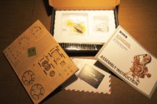
The package looked like this unopened. The light shown on the top of the box is ever so slight an exaggeration. If you were to set this projector up in the black hole of Calcutta on the night of a lunar eclipse you might see a beam of light as strong as what is portrayed on the box but I doubt it.

Upon opening I found a stack of thin plywood sheets shrink wrapped in plastic, a comprehensive instruction manual and a number of plastic bags containing parts. When I removed the shrink wrap from the plywood I found 2 full sheets of laser cut 1/4" plywood, 2 full sheets of 1/8" plywood and a half sheet of each. All that you had to do to get started was to pop out the pieces and follow the directions. Easy enough right?
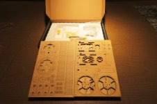
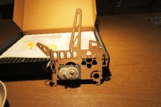
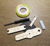
The first thing that had to be done was to screw the generator to the right side frame which was one large piece that had to be pushed out of one of the sheets of 1/4" plywood. The generator when rotated provides enough electricity to power the LED that is used to light the film strip that comes with the package. The LED comes pre-attached to the generator. A tiny little screwdriver was provided to screw in the three tiny little wood screws. The tool kit that was provided included the tiny screwdriver and some plywood tools. They also included a little square of fine sandpaper (the dark square seen in the plywood bundle on the left above).
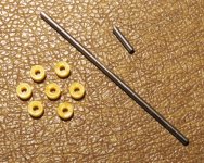
In addition to the screwdriver there was a little block of wax that is to be applied to the wooden parts that rub against each other. A roll of plastic tape was included to wrap around the film reels when they are constructed. The two wooden tools with square openings are wrenches (one open end and one box end) and were used to tighten the nuts when the crank handle was being assembled. The little piece of plywood with the notch in it to the right of the screwdriver was used to position the short pieces of 1/16" steel rod that are used as axles. The notch was just tight enough to hold the steel axle and insert it where it needed to be. Some of the positions where these tiny steel rods had to be inserted did not have enough room for a hand so the tool came in handy. The steel rods are 1/16" in diameter and came in 6 different lengths from 10mm to 65mm. Most of the rods were used as axles but some were used to strengthen connections and assemblies. The rods were retained by little orange plastic pieces that fit very snugly (they were darn hard to press onto the steel rods.).
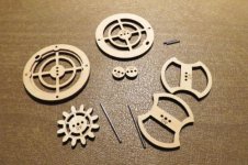
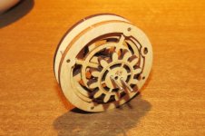
The next parts to be assembled were those for the film advance cam drive gear. This assembly controls the speed and the feed of the film strip. It is a very large assembly with many parts stacked one upon another. These are the cam parts. Notice the steel rods both long and short that are used to provide strength to the assembly. When it is complete the drive gear is on the outside and the cam is sandwiched between the two large hubs. It is impossible to see in my pictures but the hubs are held together with pegs. The pegs are rectangular on the large end and square on the small end. The peg is inserted into an oblong hole which is aligned with a round hole. When the proverbial square peg is driven into the round/oblong holes the pieces are locked together quite well. The cams had to be waxed on their exterior edges. The finished sandwich with the cam in the middle looked like the second picture below. This is the beginning of the crank assembly which drives the film through the machine. The cam parts are hidden between the two larger diameter hubs. You can see the two metal rods that help strengthen this assembly that will be transferring power from the crank when it is assembled to the rest of the drive chain. They are hard to see but the two short 10mm rods connect outer hubs and strengthen those pieces. The cam follower which is assembled later is slotted which allows it to ride over these short rods.
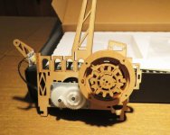
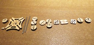
The first picture is of the assembled crank and cam attached to the right side frame of the projector. Not visible is one-half of the film advance wheel which is on the other side of the frame. The next major assembly is the film advance and axle. If you look closely you can see two pieces with 4 lobes on them on either side of two flat pieces labeled D7. Those cogs are what fit into the side slots of the film strip and pull it through the projector. The large "diamond" shaped piece on the left is the cam follower that controls the film advance one frame at a time. The perimeter of this piece had to to be saturated with wax after assembly. The two metal axles pass through all of the pieces via the two outermost holes. Yet another axle will be installed in the center hole later in the assembly process.
That is the limit for pictures in one post. I will pick up the assembly process at the next step in the next posting.
I thought I would share my experiences with this kit with pictures and descriptions. If you guys and gals don't think it is appropriate I will not post any further installments.
The package looked like this unopened. The light shown on the top of the box is ever so slight an exaggeration. If you were to set this projector up in the black hole of Calcutta on the night of a lunar eclipse you might see a beam of light as strong as what is portrayed on the box but I doubt it.

Upon opening I found a stack of thin plywood sheets shrink wrapped in plastic, a comprehensive instruction manual and a number of plastic bags containing parts. When I removed the shrink wrap from the plywood I found 2 full sheets of laser cut 1/4" plywood, 2 full sheets of 1/8" plywood and a half sheet of each. All that you had to do to get started was to pop out the pieces and follow the directions. Easy enough right?


The first thing that had to be done was to screw the generator to the right side frame which was one large piece that had to be pushed out of one of the sheets of 1/4" plywood. The generator when rotated provides enough electricity to power the LED that is used to light the film strip that comes with the package. The LED comes pre-attached to the generator. A tiny little screwdriver was provided to screw in the three tiny little wood screws. The tool kit that was provided included the tiny screwdriver and some plywood tools. They also included a little square of fine sandpaper (the dark square seen in the plywood bundle on the left above).
In addition to the screwdriver there was a little block of wax that is to be applied to the wooden parts that rub against each other. A roll of plastic tape was included to wrap around the film reels when they are constructed. The two wooden tools with square openings are wrenches (one open end and one box end) and were used to tighten the nuts when the crank handle was being assembled. The little piece of plywood with the notch in it to the right of the screwdriver was used to position the short pieces of 1/16" steel rod that are used as axles. The notch was just tight enough to hold the steel axle and insert it where it needed to be. Some of the positions where these tiny steel rods had to be inserted did not have enough room for a hand so the tool came in handy. The steel rods are 1/16" in diameter and came in 6 different lengths from 10mm to 65mm. Most of the rods were used as axles but some were used to strengthen connections and assemblies. The rods were retained by little orange plastic pieces that fit very snugly (they were darn hard to press onto the steel rods.).


The next parts to be assembled were those for the film advance cam drive gear. This assembly controls the speed and the feed of the film strip. It is a very large assembly with many parts stacked one upon another. These are the cam parts. Notice the steel rods both long and short that are used to provide strength to the assembly. When it is complete the drive gear is on the outside and the cam is sandwiched between the two large hubs. It is impossible to see in my pictures but the hubs are held together with pegs. The pegs are rectangular on the large end and square on the small end. The peg is inserted into an oblong hole which is aligned with a round hole. When the proverbial square peg is driven into the round/oblong holes the pieces are locked together quite well. The cams had to be waxed on their exterior edges. The finished sandwich with the cam in the middle looked like the second picture below. This is the beginning of the crank assembly which drives the film through the machine. The cam parts are hidden between the two larger diameter hubs. You can see the two metal rods that help strengthen this assembly that will be transferring power from the crank when it is assembled to the rest of the drive chain. They are hard to see but the two short 10mm rods connect outer hubs and strengthen those pieces. The cam follower which is assembled later is slotted which allows it to ride over these short rods.


The first picture is of the assembled crank and cam attached to the right side frame of the projector. Not visible is one-half of the film advance wheel which is on the other side of the frame. The next major assembly is the film advance and axle. If you look closely you can see two pieces with 4 lobes on them on either side of two flat pieces labeled D7. Those cogs are what fit into the side slots of the film strip and pull it through the projector. The large "diamond" shaped piece on the left is the cam follower that controls the film advance one frame at a time. The perimeter of this piece had to to be saturated with wax after assembly. The two metal axles pass through all of the pieces via the two outermost holes. Yet another axle will be installed in the center hole later in the assembly process.


That is the limit for pictures in one post. I will pick up the assembly process at the next step in the next posting.
