new cnc machine startover post....

checked with the cnc people to which power supply to use, as i have 2 of them. also found out that the silent spindle can be outfitted with both the 1/8" and 1/4" collets. nice to be able to use a beefier mill every now and then. also did a double check of how it stands, and i have 7 more steps to go before i can fire it up for the first time.
 
well, after a rough couple of days, got back to it and finished off the wiring. then, the frankenstein moment when i applied power to the machine, and it fired right up. with a lot of help from bill, got it to run the test in the right direction (first run was upside down and reading from right to left). i think the next test will be to give this a try with the spindle up and running, and carve on some scrap lumber.
 

Attachments

  • 054 ready for testing a.jpg
    054 ready for testing a.jpg
    128.9 KB · Views: 13
  • 055 ready for testing b.jpg
    055 ready for testing b.jpg
    133.5 KB · Views: 12
  • 056 finished first test.jpg
    056 finished first test.jpg
    82.6 KB · Views: 14
Looks like everything is headed the right direction now, Dan! I'm glad I was able to help last night. It was easy to sound like I know what I was talking about since I had to resolve the same issues. ;) It's been great to bounce things off of each other during our builds. Now to see what we can make with these things!!!
 
needed to add another layer of mdf to raise the bed to where it ought to be. it cut the shapeoko test just nice, but everything else is still messed up.
 

Attachments

  • 057 second base layer added.jpg
    057 second base layer added.jpg
    115.1 KB · Views: 11
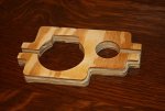
been a while, but here goes. checked out my think sign, after checking with the shapeoko people to make sure that i had my x axis, and y axis going in the right directions, and finally took a video of what it was doing. right off from the 0 points, the spindle goes to the right on the x axis, and tries to go past the rail, after a few seconds it goes back to a certain point, then makes what appears to be a lap around the perimeter of the sign, then does the lettering first pass, around the perimeter again, then the second pass on the lettering, then clears out the center of the lettering, yet another pass around the perimeter, then goes back to the original 0 point. they think it could be something messed up in the gcode. we shall see. after doing this, i dismounted the spindle and such, and replaced the bad delrin nut, much better now. now i have to zip the video file so it can be sent to them, too big to be sent now, at a little over 13 minutes long.
 
When I saw your g-code it looked like it was in metric. I saw numbers like 127.something

Also, I would like to see how you are generating the code.

Is you "think" sign being gode generated horizontal (long axis=x) or vertical (long axis=y)?

It is really hard to see what is going on just by looking at the machine axis moving, without cutting.

When the "X" axis is bouncing at the end - the coordinates might be getting knocked out of whack.

Before trying to solve any of that though -

I will still recommend making a simple basic program that does nothing more that to cut a single line 6" long

That g-code would look like this:

G0 X0 Y0
Z1.0
G1 Z0 F20.0
X6.00
Z.1
G0 Z1.0

With code like this you can easily SEE "exactly" what is going on.

You can also measure how far the axis is moving to determine if it is doing what it should be doing.

After you get the machine to do a simple thing like this, THEN, go on to something a little bigger.

NEXT you make a 6" square - that code would look like this:

G0 X0 Y0
Z1.0
G1 Z0 F20.0
X6.00
Y6.00
X0
Y0
Z.1
G0 Z1.0

Doing a diagnostic in this way is essential to getting this figured out.

If you try solving the problem by trying to make a sign - you will be fighting this and maybe get so frustrated that you will begin to hate CNC.

I have done this for a living for 30 years and have trained dozens of CNC machinists and 10's of CNC engineers. I am 100% certain that if you don't go to the simple basics - you will be fighting this ever step of the way. DO AHIKT! BTDT - many many times

Even as a 30 year veteran of CNC - I will write program to make a line and a box - and then a circle. This is by far the very best method.

You will notice - even the inventables people did not offer up a real solution.

Please try what I have suggested - then - I can teach and lead you into the places where you want to go.

Trust me - I have taught MANY people how to do this stuff.

This is one of the things I do for a living.
 
So,

Looking at your program and converting to Imperial inch this is what the machine is doing at the beginning:


Dan Noren Program.jpg


I have added the text converted to the first section of your program.


Dan Noren Program-2.jpg

The machine is moving in the "X" axis to the right 25.107 inches - or at least trying to.

I suspect that the machine is not that wide in "X" - and at the mechanical limit of the "X" axis the stepper motor is just losing steps - that is the bouncing. That is NOT healthy for the machine and you should not continue doing that.

After that is starts moving to what it "thinks" is the next point - BUT - it is now out of it calibrated coordinates due to losing steps.

Your program is in metric, but I think your machine is setup for inch. I don't really know. OR - you are working in metric, both programming and also on the machine - I don't know.

You may be thinking in inches and not sure of the g-code and what is means - I don't know.

Dan - you REALLY need to get back to basics, before moving on.
 
Excellent post and advice Leo. You da man. We lucky to have your talent around and you being willing to help a fellow woodworker. Sometimes all a person needs is a redirect back to kiss system. This is what i truly appreciate about our forum.

Sent from my SGH-I337M using Tapatalk
 
i did this test just for the fun of it, as they wanted a vid of what was happening. the funny thing is, is that after the initial bump and grind, it ran around the perimeter of the sign at the right size, and ran all of the letters correctly (one of those had to be there things i guess). then did the bump and grind on the left side, and then stopped at the original zero point.
 
nope, not satisfied at all. still have to work out the bumps....

I feel your pain, Dan. I'm sure you'll get it worked out. If you haven't already joined the Shapeoko forum, you should do so. We have good resources here and the SO forum has lots of folks with direct experience with the machines you and I have.

I've been working on a calibration issue - fine tuning, really. I had to tweak the X and Y steps/mm because the axes were moving a bit more than they should. It appeared to be dead on after I adjusted the values, but a project I ran yesterday is a tiny bit under-sized. I'm on my way back out to my shop to check my calibration a bit more.

Hang in there!
 
success!!!!!!! today i reset the position of the maker slide for the z axis, and tightened up the belts even more. then i tried the code that leo had set out, but it only moved about an inch and a quarter. so i called the inventables gang, and we put in g20, to tell it that it was inches and not mm, and voila! (a little french lingo there), it worked! it went the full 6 inches along the x axis, then the full 6 inches along the y axis (you talk about a happy monkey here). then i decided to really put it to the test, and use the g code for the bracket that bill came up with. that worked out rather well (on the second go round, as on the first, i didn't hold it down too good). a big thanks to both leo and bill for all their help with this. now to see what manner of mischief i can get into with this machine....
 

Attachments

  • 058 first item off the cnc machine.jpg
    058 first item off the cnc machine.jpg
    93.5 KB · Views: 9
Top