- Messages
- 8,631
- Location
- Thomasville, GA
OK, so I received my package last Thursday evening via FedEx. It appeared to be in good shape, so I cut the tape, opened the box and removed the three styrofoam trays holding the parts. Everything looked well-protected and in great shape.
The acrylic parts are protected with a paper/plastic material that I found fairly easy to remove, although it was tedious as heck! I did that process Thursday evening.
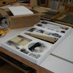
Day One of actual build (Friday):
The first step was screwing the uprights and their supports together. Exciting, huh?
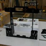
At the end of the day on Friday, I had gone through step 9 of 27 and is was 5:00 - somewhere.

Day Two (Saturday):
Steps 10 through 18 were done in the morning. That got me to the point of having the bed support and Y belt installed, as well as the Z motors with associated lead screws and guide rods.
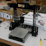
I continued in the afternoon, getting the extruder and its fans installed, along with the X motor and belt. I also started getting the wiring routed through the system.
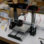
Monday
Not a lot to report today. I got the H-frame flipped as per Darren's link. LOML said I needed to take her to lunch and I know who the real boss is! I wanted to look at storage containers and get something for the 3D printer filament, so we had lunch at the Chinese buffet next door to Walmart, then toured WallyWorld. By the time we got back home, I was ready for a nap; stayed up too late watching football Sunday night, I guess!
Tuesday
Mounted the system board to the printer and routed cables to it. Got some of the cables contained in cable wrap. Made sure of all connections and turned the system on. Everything appeared good, so I did a homing run. That's when I discovered an issue with the Z-axis endstop switch; it would have allowed the extruder nozzle to hit the table if it weren't already aligned off the lower left. So, I adjusted the switch mount higher to take care of that problem. Next, I researched the Z-axis issue and found lots of solutions to allow for fine adjustments to Z.
Another issue I had was mounting the 12VDC power supply. Unless I'm missing something, there aren't any holes in the right locations to match the two slots on the power supply case. Easy enough to solve with a drill.
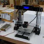
That's enough for today. I ended up playing plumber like Jim Delaney, although nowhere near as serious as his problems!
Just as I was closing down for the day, Bobbie came down the driveway with the mail delivery. I now have the MOSFET to offload the heat bed from the system board along with the capacitive leveling sensor. More fun tomorrow!
Wednesday
Today was mostly a bust as far as progress on the printer is concerned. I had an appointment with my cardiologist at 9:45am; had to be there at 9:30. Finally got taken to an exam room at 10:05; 10:45 the doctor still wasn't in there, so I opened the door to let them know I had another life. Finally, about five minutes later the doctor came in. They had a couple of emergencies, etc., etc., etc. Anyway, I finally got back home about 11:30 - in time for lunch!
Then, LOML reminded me we (we?) needed to get the bat house up, so I ran to Lowe's for some sticks of PVC pipe. Got everything all set up and she helped me swing the thing up in the air.
Thursday
I started the day getting the MOSFET heat bed switch installed. Then I started testing some functions. When I turned on the heat bed, I heard the fan slow down so I started checking the power supply voltage. I knew it had been about 12.1VDC with no load and the adjustment worked.
On further review...turned out to be a headspace problem. I thought I had switched the power supply to 110VAC, but had not done so. All is well in electron land now, so we'll see what the afternoon brings!
Friday
Today, I did a lot of reading to try to understand all the steps necessary to get a file printed.
I spent quite a while getting the bed leveled, then was ready for the next steps. When I loaded filament into my printer for the first time, it appeared to bottom out but I didn't get anything from the nozzle. So, I disassembled the extruder to see what was going on. There was a slight misalignment between the stepper and the opening to the nozzle, so I loosened the bolts and wiggled the parts around a little. Got that going just fine with a good stream of PLA from the nozzle. I chose a gcode file that was on the SD card and started it after doing a Home All. The nozzle was about 0.2mm above the bed at the 0,0 location. As the print started, it moved about 3mm above the table, went to the starting point and stayed above the table, not returning to the Z0 location or 0.2mm. The resultant print is shown in the photo. I stopped the print after a few seconds.

I need to go through CURA and see how it operates and create my own gcode file based on my machine to see if that fixes the print.
Any thoughts?
I'll keep adding updates to this post rather than in replies.
The acrylic parts are protected with a paper/plastic material that I found fairly easy to remove, although it was tedious as heck! I did that process Thursday evening.

Day One of actual build (Friday):
The first step was screwing the uprights and their supports together. Exciting, huh?

At the end of the day on Friday, I had gone through step 9 of 27 and is was 5:00 - somewhere.

Day Two (Saturday):
Steps 10 through 18 were done in the morning. That got me to the point of having the bed support and Y belt installed, as well as the Z motors with associated lead screws and guide rods.

I continued in the afternoon, getting the extruder and its fans installed, along with the X motor and belt. I also started getting the wiring routed through the system.

Monday
Not a lot to report today. I got the H-frame flipped as per Darren's link. LOML said I needed to take her to lunch and I know who the real boss is! I wanted to look at storage containers and get something for the 3D printer filament, so we had lunch at the Chinese buffet next door to Walmart, then toured WallyWorld. By the time we got back home, I was ready for a nap; stayed up too late watching football Sunday night, I guess!
Tuesday
Mounted the system board to the printer and routed cables to it. Got some of the cables contained in cable wrap. Made sure of all connections and turned the system on. Everything appeared good, so I did a homing run. That's when I discovered an issue with the Z-axis endstop switch; it would have allowed the extruder nozzle to hit the table if it weren't already aligned off the lower left. So, I adjusted the switch mount higher to take care of that problem. Next, I researched the Z-axis issue and found lots of solutions to allow for fine adjustments to Z.
Another issue I had was mounting the 12VDC power supply. Unless I'm missing something, there aren't any holes in the right locations to match the two slots on the power supply case. Easy enough to solve with a drill.

That's enough for today. I ended up playing plumber like Jim Delaney, although nowhere near as serious as his problems!
Just as I was closing down for the day, Bobbie came down the driveway with the mail delivery. I now have the MOSFET to offload the heat bed from the system board along with the capacitive leveling sensor. More fun tomorrow!
Wednesday
Today was mostly a bust as far as progress on the printer is concerned. I had an appointment with my cardiologist at 9:45am; had to be there at 9:30. Finally got taken to an exam room at 10:05; 10:45 the doctor still wasn't in there, so I opened the door to let them know I had another life. Finally, about five minutes later the doctor came in. They had a couple of emergencies, etc., etc., etc. Anyway, I finally got back home about 11:30 - in time for lunch!
Then, LOML reminded me we (we?) needed to get the bat house up, so I ran to Lowe's for some sticks of PVC pipe. Got everything all set up and she helped me swing the thing up in the air.
Thursday
I started the day getting the MOSFET heat bed switch installed. Then I started testing some functions. When I turned on the heat bed, I heard the fan slow down so I started checking the power supply voltage. I knew it had been about 12.1VDC with no load and the adjustment worked.
On further review...turned out to be a headspace problem. I thought I had switched the power supply to 110VAC, but had not done so. All is well in electron land now, so we'll see what the afternoon brings!
Friday
Today, I did a lot of reading to try to understand all the steps necessary to get a file printed.
I spent quite a while getting the bed leveled, then was ready for the next steps. When I loaded filament into my printer for the first time, it appeared to bottom out but I didn't get anything from the nozzle. So, I disassembled the extruder to see what was going on. There was a slight misalignment between the stepper and the opening to the nozzle, so I loosened the bolts and wiggled the parts around a little. Got that going just fine with a good stream of PLA from the nozzle. I chose a gcode file that was on the SD card and started it after doing a Home All. The nozzle was about 0.2mm above the bed at the 0,0 location. As the print started, it moved about 3mm above the table, went to the starting point and stayed above the table, not returning to the Z0 location or 0.2mm. The resultant print is shown in the photo. I stopped the print after a few seconds.

I need to go through CURA and see how it operates and create my own gcode file based on my machine to see if that fixes the print.
Any thoughts?
I'll keep adding updates to this post rather than in replies.
Last edited:


