
- Messages
- 36,134
- Location
- ABQ NM
If you’ve been following along, you’ll know I got a new compressor last week. Before I got the compressor, I spent a couple weeks worth of evenings researching and building an air line system to hook it up to.
I’ll be the first to admit that what I built is bigtime overkill for my current needs, and is likely more than I’ll ever need in this shop. If I were doing production work, then a system like this might be warranted, but for my evening and weekend use, I went a bit overboard. Still, I figured a decent compressor deserves a decent air delivery system to go with it. And when I eventually move into a bigger shop, most of this will be able to go with me.
The system consists of two main parts: the drying/cooling rack and the air station. The drying rack is intended to cool and thus help dry the air on its way to the air station. The air station is where I have a couple outlets on separate regulators, and that’s where most tools will be plugged into the compressor.
Here’s the sketch of the drying rack:
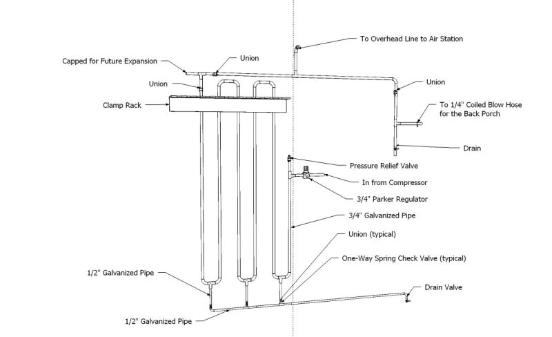
And here’s how it looked partway through the build. This was at a stage where I was pressure testing it for leaks, so there are some valves, gauges, and plugs that aren’t in the final installation:

The rack was initially assembled on the floor, and the 2x2 wood pieces were attached then, to keep it from twisting as I moved it around. Next, I lag bolted the horizontal 2x4s through the stucco to the studs, positioning them so I could simply set the 2x2s attached to the pipes on the 2x4s and screw them in place from the top. Sort of a French cleat, without the angled parts. Since I needed to attach my clamp rack over the piping, I used vertical 2x4s as standoffs, again lagged to the wall studs. Here’s how it looks with the clamps in place:

And a bit more detail of the gate valves and the horizontal drain collection tube. (This pic was taken after installing the final valve at the end of the line.)

Once the compressor was installed, it became difficult to get any photos of the drying rack, so these in-progress pics will have to do. Now…on to the rest of the system.
The air exits the compressor via a 3/4" ball valve into a 3/4” ID flex hose:

From there, it goes 5’ to a Parker regulator, which is attached to the drying rack. I've capped the line at the point where I plan to install a pressure relief valve:

And a bit more detailed look at the regulator:

After the air goes through the rack, it goes to the overhead line and to the air drop by the door. I put it there so we can use the air hose to sweep the back porch and patio. In this pic you can see the 40 amp disconnect I installed for the compressor. I didn’t really need it, but it didn’t add much to the cost, and it gives me a convenient location from which to kill power to the compressor. This is also where the drain valve is located for emptying the water out of the drying rack. I’ll probably put a flex hose on this valve so I can blow the water outside:

There’s also the overhead pipe run, which goes from the drying rack across the shop to the air station. It has a jog in it to miss the ambient air filter:

More red flex hose takes the air down to the air station near the end of my lathe, which is where the vast majority of my air use happens.
And here’s the air station. It’s got a Beach filter/desiccant dryer (retails for over $1000 with the extra bleeder valve…I got it on eBay for $50), and a pair of Harbor Freight mini-filter/regulators. Using dual regulators lets me run the sander at 85 PSI and the blower nozzle at 125 PSI or so.

And another, more detailed shot. The whole thing is attached to a piece of scrap OSB I had laying around, and the OSB is attached to the side of my metal rolling drawer cabinet/workbench:

The red flex hose was not my original choice. When I initially hooked everything up, I used 5/8” ID clear plastic hose with nylon braid in it {rated at 200 PSI), attached to hose barbs with standard hose clamps. When first I pumped up the system to 135 PSI, I had some small leaks at the clamped connections, so starting at the compressor, I tightened up each joint until the leaks stopped. When I got to the last fitting, where the hose attaches to the air station, I bent down to tighten the clamp, and just as I was starting to tighten it, BLAM! the hose blew off the hose barb, and became an angry snake hanging from the ceiling, trying to take my head off. I did have the presence of mind to duck as I ran away trying to get out of the range of the whip. It did end up whacking me pretty good in the arm, and it felt like it punched me in the face. Later examination indicated that the hose itself didn’t hit my face, since there were no bruises or other marks. I’m guessing it was the blast of air that just felt like a fist. Whatever it was, it blew my prescription safety glasses off my face and out into the driveway. (I was standing at nearly the back wall of the garage.)
That experience caught my attention, and made me not trust the clamped fittings. The hose didn’t rupture, but for reasons I still haven’t figured out, the clamp stopped clamping. Even the guy at the hose shop where I bought the red hoses couldn’t understand how the hose blew off the fitting. He said it sounded like I did everything right. All I know is that I’m no longer comfortable with that type of fitting, so I bought beefier hoses, with machine-crimped male pipe fittings on both ends. I know a lot of folks have had good success with hose clamps and barb fittings, but no more for me, thanks.
After I got the red hoses installed, I pressured everything back up, and after checking all the joints with soapy water, I only found a few small leaks, which I’ve now tightened up to my satisfaction.
As I mentioned earlier, this system is overkill for my current needs (just running a little 2” sander and a blow nozzle), but if I decide to run a sandblaster or spray gun or die grinder in the future, I should have plenty of clean, dry air at the tool.
That’s it for the delivery system…thanks for following along. I’ll post pics of the compressor and its installation in another post.
Comments and questions are welcome.
I’ll be the first to admit that what I built is bigtime overkill for my current needs, and is likely more than I’ll ever need in this shop. If I were doing production work, then a system like this might be warranted, but for my evening and weekend use, I went a bit overboard. Still, I figured a decent compressor deserves a decent air delivery system to go with it. And when I eventually move into a bigger shop, most of this will be able to go with me.
The system consists of two main parts: the drying/cooling rack and the air station. The drying rack is intended to cool and thus help dry the air on its way to the air station. The air station is where I have a couple outlets on separate regulators, and that’s where most tools will be plugged into the compressor.
Here’s the sketch of the drying rack:
And here’s how it looked partway through the build. This was at a stage where I was pressure testing it for leaks, so there are some valves, gauges, and plugs that aren’t in the final installation:
The rack was initially assembled on the floor, and the 2x2 wood pieces were attached then, to keep it from twisting as I moved it around. Next, I lag bolted the horizontal 2x4s through the stucco to the studs, positioning them so I could simply set the 2x2s attached to the pipes on the 2x4s and screw them in place from the top. Sort of a French cleat, without the angled parts. Since I needed to attach my clamp rack over the piping, I used vertical 2x4s as standoffs, again lagged to the wall studs. Here’s how it looks with the clamps in place:
And a bit more detail of the gate valves and the horizontal drain collection tube. (This pic was taken after installing the final valve at the end of the line.)
Once the compressor was installed, it became difficult to get any photos of the drying rack, so these in-progress pics will have to do. Now…on to the rest of the system.
The air exits the compressor via a 3/4" ball valve into a 3/4” ID flex hose:
From there, it goes 5’ to a Parker regulator, which is attached to the drying rack. I've capped the line at the point where I plan to install a pressure relief valve:
And a bit more detailed look at the regulator:
After the air goes through the rack, it goes to the overhead line and to the air drop by the door. I put it there so we can use the air hose to sweep the back porch and patio. In this pic you can see the 40 amp disconnect I installed for the compressor. I didn’t really need it, but it didn’t add much to the cost, and it gives me a convenient location from which to kill power to the compressor. This is also where the drain valve is located for emptying the water out of the drying rack. I’ll probably put a flex hose on this valve so I can blow the water outside:
There’s also the overhead pipe run, which goes from the drying rack across the shop to the air station. It has a jog in it to miss the ambient air filter:
More red flex hose takes the air down to the air station near the end of my lathe, which is where the vast majority of my air use happens.
And here’s the air station. It’s got a Beach filter/desiccant dryer (retails for over $1000 with the extra bleeder valve…I got it on eBay for $50), and a pair of Harbor Freight mini-filter/regulators. Using dual regulators lets me run the sander at 85 PSI and the blower nozzle at 125 PSI or so.
And another, more detailed shot. The whole thing is attached to a piece of scrap OSB I had laying around, and the OSB is attached to the side of my metal rolling drawer cabinet/workbench:
The red flex hose was not my original choice. When I initially hooked everything up, I used 5/8” ID clear plastic hose with nylon braid in it {rated at 200 PSI), attached to hose barbs with standard hose clamps. When first I pumped up the system to 135 PSI, I had some small leaks at the clamped connections, so starting at the compressor, I tightened up each joint until the leaks stopped. When I got to the last fitting, where the hose attaches to the air station, I bent down to tighten the clamp, and just as I was starting to tighten it, BLAM! the hose blew off the hose barb, and became an angry snake hanging from the ceiling, trying to take my head off. I did have the presence of mind to duck as I ran away trying to get out of the range of the whip. It did end up whacking me pretty good in the arm, and it felt like it punched me in the face. Later examination indicated that the hose itself didn’t hit my face, since there were no bruises or other marks. I’m guessing it was the blast of air that just felt like a fist. Whatever it was, it blew my prescription safety glasses off my face and out into the driveway. (I was standing at nearly the back wall of the garage.)
That experience caught my attention, and made me not trust the clamped fittings. The hose didn’t rupture, but for reasons I still haven’t figured out, the clamp stopped clamping. Even the guy at the hose shop where I bought the red hoses couldn’t understand how the hose blew off the fitting. He said it sounded like I did everything right. All I know is that I’m no longer comfortable with that type of fitting, so I bought beefier hoses, with machine-crimped male pipe fittings on both ends. I know a lot of folks have had good success with hose clamps and barb fittings, but no more for me, thanks.
After I got the red hoses installed, I pressured everything back up, and after checking all the joints with soapy water, I only found a few small leaks, which I’ve now tightened up to my satisfaction.
As I mentioned earlier, this system is overkill for my current needs (just running a little 2” sander and a blow nozzle), but if I decide to run a sandblaster or spray gun or die grinder in the future, I should have plenty of clean, dry air at the tool.
That’s it for the delivery system…thanks for following along. I’ll post pics of the compressor and its installation in another post.
Comments and questions are welcome.


