Jim C Bradley
Member
- Messages
- 4,945
My son Glenn accuses me of doing things, HOWEVER (Notice that is a big However), without posting. So here is what I have been doing the last day and a half (Besides going to the Dr., having a Latte with Myrna, going out to dinner, cleaning the spa, repairing the broken sprinkler, etc.).
I needed a steady rest. I looked thru the books and mags. I found one that looked simple, not something for show. The following is how the story unrolled.
The one I chose had the following advantages:
It was a convenient size and would be easy to store.
It was basically made of three-quarter inch plywood.
The disadvantages were:
It required a lot of bandsaw or scrollsaw work.
It had lots of corners and curves that would have to be sanded.
To make it would require more time than something simpler.
What I did:
I eliminated all of the cutouts and nice looking curved design factors.
I did stay with the book’s dimensions and materials for the “arms”, the size of the base and all the other important measurements.
I simplified the base from 5 pieces of wood to three.
I eliminated the mortise and tenon factor.
First I drew an outline of the unit shown in the book...sort of like drawing an irregular box around a bunch of circles and arcs. I cut the outline out on the BS (other tools would have worked just as well).
Then I placed a nice pointy drive in the lathe headstock,
Pic #1
I held my plywood board in it’s proper location on the ways and banged it with my fist. This left a nice hole in the ply at the center of turning rotation.
Pic #2
All of the other dimensions were made from this reference Point (pardon the pun) because the turning has to clear the ply and the wheels have to hold the turning so it rotates around the point. The pic shows the roughed out plywood piece the way that it will sit on the ways.
Pic #3
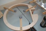
The next picture shows that you need to think when you are using dimensions from a plan, magazine, book or whatever. It is a little difficult to tell from the photo, however, with the arms closed in as far as they will go, the smallest wood they will hold in place is two inches in diameter. I didn’t catch that and made the arms in the pic (the size specified in the drawing). Well I got to make another set of arms---each one an inch longer than specified on the drawing. Do Not completely trust dimensions in a drawing---Think while you work---I didn’t and had the opportunity to do some extra woodworking.
Pic #4
The system for holding the arms consists of three knobs (or whatever) to tighten the arms in place, and three “guide” pins to keep the arms from moving in undesired ways. I used six 1 / 4 x 20 inserts. Three of these were used for a place for the knobs to tighten into...Three were to hold the 1 / 4 x 20 threaded guide pins.
The guide pins were made by cutting the head off of stove bolts---see pic. The reason for the nut in the picture is my father. When I was a very young kid, dad told me to always put a nut on any threaded device that I was going to shorten. That way after cutting it off, I could run the nut off clearing the threads of burrs, etc. I chose bolts that had a smooth collar below the head and the cut off the other end to the desired length.
Pic #5
The next pic shows the ply with the three inserts for the guides with one guide temporarily screwed into place.
Pic #6
Pic #7
The pic after that shows inserting the insert using the drill press for a nice “true to the world” insertion of the insert. When I was a kid there was a very famous comedian named Bob Hope (I met him once). In one of Bob’s movies his character’s name was Lawrence, Lawrence, Lawrence. The character said that was his name because his mother didn’t have any imagination.
Pic #8
The insertion tool is a sawed off, cheap screwdriver ground to fit the slot in the insert. By using the drill press I could put steady, very firm down pressure with my right hand while turning the chuck slowly with my left hand. This makes a very neat, true insertion and does not raise any of the surface wood (DAMHIKT). Guess why I made the custom screwdriver for this kind of job.
The pic of the, just begun, steady rest with the “hold down” block is a picture of my measuring stupidity. The crosspiece that goes under the lathe rails fits beautifully---unless you want to move it over a few inches. It is too long to go between the rail braces so be careful where you measure for yours. You now know why I can’t get too ticked off about the wrong measurement in the book drawing that I worked from.
Pic #9
In my case there is a 5-inch, 5 / 16 diameter bolt which goes thru the steady rest, between the rails, through the anti-rotation block, through the cross-piece hold down and into a Tee Nut. Now you know why there was a notch cut in the plywood...so a socket or spin-tight wrench can lock the unit into the desired place on the lathe and the bolt head would not impinge on the space for the turning wood.
And, at last, we have the finished (but not yet finished) steady rest on the lathe. Notice the little block between the ways. The block is screwed to the bottom of the steady rest and prevents rotation. It goes across the entire base. The block is a close, however, loose fit between the ways. Close so it won’t move, loose so it isn’t a pain to place in position.
Pic #10
The nylon wheels will go closer together than shown in the photo. They can actually touch each other and that is a lot better than having the turned piece be at least two inches in diameter at the steady rest.
Enjoy,
Jim
I needed a steady rest. I looked thru the books and mags. I found one that looked simple, not something for show. The following is how the story unrolled.
The one I chose had the following advantages:
It was a convenient size and would be easy to store.
It was basically made of three-quarter inch plywood.
The disadvantages were:
It required a lot of bandsaw or scrollsaw work.
It had lots of corners and curves that would have to be sanded.
To make it would require more time than something simpler.
What I did:
I eliminated all of the cutouts and nice looking curved design factors.
I did stay with the book’s dimensions and materials for the “arms”, the size of the base and all the other important measurements.
I simplified the base from 5 pieces of wood to three.
I eliminated the mortise and tenon factor.
First I drew an outline of the unit shown in the book...sort of like drawing an irregular box around a bunch of circles and arcs. I cut the outline out on the BS (other tools would have worked just as well).
Then I placed a nice pointy drive in the lathe headstock,
Pic #1
I held my plywood board in it’s proper location on the ways and banged it with my fist. This left a nice hole in the ply at the center of turning rotation.
Pic #2
All of the other dimensions were made from this reference Point (pardon the pun) because the turning has to clear the ply and the wheels have to hold the turning so it rotates around the point. The pic shows the roughed out plywood piece the way that it will sit on the ways.
Pic #3
The next picture shows that you need to think when you are using dimensions from a plan, magazine, book or whatever. It is a little difficult to tell from the photo, however, with the arms closed in as far as they will go, the smallest wood they will hold in place is two inches in diameter. I didn’t catch that and made the arms in the pic (the size specified in the drawing). Well I got to make another set of arms---each one an inch longer than specified on the drawing. Do Not completely trust dimensions in a drawing---Think while you work---I didn’t and had the opportunity to do some extra woodworking.
Pic #4
The system for holding the arms consists of three knobs (or whatever) to tighten the arms in place, and three “guide” pins to keep the arms from moving in undesired ways. I used six 1 / 4 x 20 inserts. Three of these were used for a place for the knobs to tighten into...Three were to hold the 1 / 4 x 20 threaded guide pins.
The guide pins were made by cutting the head off of stove bolts---see pic. The reason for the nut in the picture is my father. When I was a very young kid, dad told me to always put a nut on any threaded device that I was going to shorten. That way after cutting it off, I could run the nut off clearing the threads of burrs, etc. I chose bolts that had a smooth collar below the head and the cut off the other end to the desired length.
Pic #5
The next pic shows the ply with the three inserts for the guides with one guide temporarily screwed into place.
Pic #6
Pic #7
The pic after that shows inserting the insert using the drill press for a nice “true to the world” insertion of the insert. When I was a kid there was a very famous comedian named Bob Hope (I met him once). In one of Bob’s movies his character’s name was Lawrence, Lawrence, Lawrence. The character said that was his name because his mother didn’t have any imagination.
Pic #8
The insertion tool is a sawed off, cheap screwdriver ground to fit the slot in the insert. By using the drill press I could put steady, very firm down pressure with my right hand while turning the chuck slowly with my left hand. This makes a very neat, true insertion and does not raise any of the surface wood (DAMHIKT). Guess why I made the custom screwdriver for this kind of job.
The pic of the, just begun, steady rest with the “hold down” block is a picture of my measuring stupidity. The crosspiece that goes under the lathe rails fits beautifully---unless you want to move it over a few inches. It is too long to go between the rail braces so be careful where you measure for yours. You now know why I can’t get too ticked off about the wrong measurement in the book drawing that I worked from.
Pic #9
In my case there is a 5-inch, 5 / 16 diameter bolt which goes thru the steady rest, between the rails, through the anti-rotation block, through the cross-piece hold down and into a Tee Nut. Now you know why there was a notch cut in the plywood...so a socket or spin-tight wrench can lock the unit into the desired place on the lathe and the bolt head would not impinge on the space for the turning wood.
And, at last, we have the finished (but not yet finished) steady rest on the lathe. Notice the little block between the ways. The block is screwed to the bottom of the steady rest and prevents rotation. It goes across the entire base. The block is a close, however, loose fit between the ways. Close so it won’t move, loose so it isn’t a pain to place in position.
Pic #10
The nylon wheels will go closer together than shown in the photo. They can actually touch each other and that is a lot better than having the turned piece be at least two inches in diameter at the steady rest.
Enjoy,
Jim
Last edited:

 Using the studs as guides for the three arms it a brilliant solution.
 Why hasn't it gone so smooth for me??
 Wanna sell one????